It's time to take apart a triple valve so we can clean and lubricate it. This will insure that it continues to operate properly, otherwise we may regret it. First, let's prepare a clean surface to work on.
This is a Westinghouse M2A triple valve with graduated release, quick recharge, and quick action features. We'll see what that means later.
This is a Westinghouse M2A triple valve with graduated release, quick recharge, and quick action features. We'll see what that means later.
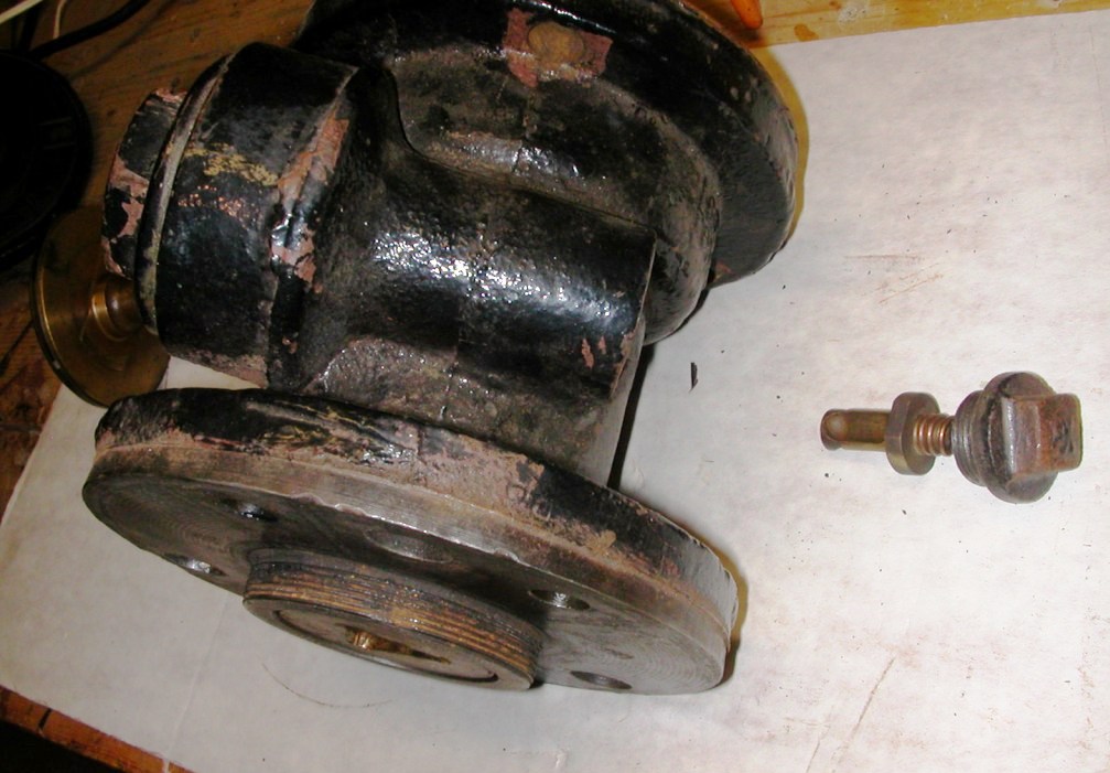
 Here are two views of the complete triple as removed from the pipe bracket. The valve is held to the bracket with three bolts, and there is a rubber gasket (#9356) to make a nice reliable seal for all the various ports.
The view to the right shows the ports of various sizes and shapes in the face of the triple valve body.
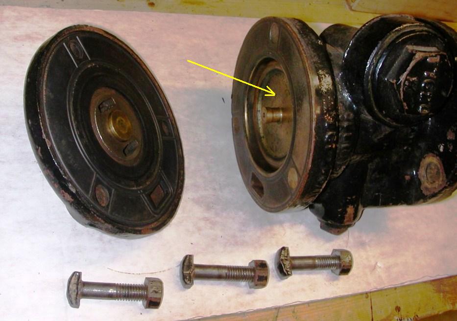 At the other end of the body is the cylinder cap, held by three special bolts. It also has a gasket (#131A) to seal it to the body. Fortunately this appears to be in excellent condition. Inside the cylinder you can see the face of the piston (yellow arrow).
Here the piston assembly has been pulled part way out, so you can clearly see the piston itself. It has a brass slip ring to seal it to the cylinder. Diameter is 3 1/2".
 The piston assembly is the most important part of the valve. The piston and its stem (black arrow)are on top. Below that is the slide valve (blue arrow) which wraps around the stem and is held down by a leaf spring. There is also a graduating valve, which you can barely see (red arrow) which rides on top of the inner part of the slide valve. The graduating valve can move back and forth about 5/16" over the slide valve.
Here is the bottom surface of the slide valve. We're not meant to know what all these various little ports do - that will cost you extra. The main point is this: a slight difference in pressure on the piston will cause it to move the graduating valve over the slide valve, but a greater difference in pressure is needed to move the slide valve itself, due to the greater friction.

And here's a view of the cylinder. You can see the square cutout at the bottom; this is where the slide valve moves, and you can see some ports in the floor of the cylinder which line up with the slide valve as it moves back and forth.

The other part of the system we need to check is the quick-action portion, shown here in the yellow rectangle. This needs to be cleaned, but we are advised not to lubricate it because it is used so seldom. 
Well, I can remove the small end of the quick-action valve; here we see the cap, spring, and plug. But the big end seems to be frozen. Maybe some penetrating oil will do its magic. So we wait.... (to be continued).
Meanwhile, let's ponder what all these parts are supposed to do. The motorman charges the system by putting his motorman's valve into release; this charges the brake pipe up to control pipe pressure, 70 psi.
1. If the brake pipe pressure is greater than that in the auxiliary reservoir, the triple valve piston will be pushed all the way into the body, into Release and Recharge position. The triple then releases any brake cylinder pressure to atmosphere, and sends air from the brake pipe and the control pipe into the auxiliary reservoir, to charge it to 70 psi. The brakes are released, so we can move the train. The control pipe provides the quick recharge feature, so the reservoir will be filled quickly.
2. To slow down or stop, the motorman reduces (at a moderate rate) the pressure in the brake pipe. Since the auxiliary now has higher pressure than the brake pipe, the piston moves out to Service position. Air from the auxiliary reservoir flows into the brake cylinder (which can no longer exhaust). So the brakes come on.
3. For a moderate brake reduction, such as 10 psi, the pressure in the auxiliary at some point will drop slightly below the brake pipe. The piston then moves in, taking the graduating valve with it, but stopping when it hits the slide valve. We are now in Service Lap and all ports are closed.
To increase the braking force, a further reduction in brake pipe pressure can be made, so the triple goes back to Service, then Service Lap again.
The parts are proportioned so that when the auxiliary drops to about 50 psi, the brake cylinder has risen to 50 psi, and they are equalized. This is the maximum brake pressure you can get in Service position. Any further (service) reduction will accomplish nothing.
4. To release the brakes, the brake pipe pressure is increased. The triple moves into Release and Recharge, and the auxiliary pressure starts to increase. If we don't want to release all the way, but just reduce the brake cylinder pressure, that's called graduated release. The auxiliary pressure will rise above the brake pipe because the control pipe always supplies 70 psi, and the piston will move out slightly. But this time, it stops when it hits the slide valve, and we are now in Release Lap. The port connecting the brake cylinder to exhaust is closed, so the brake cylinder pressure stops decreasing. Without the control pipe, graduated release would not be possible. We can partially reduce the braking pressure by increasing the brake pipe, and the triple will move between Release and Release Lap.
5. Finally, there's the quick action feature. In an emergency, the brake pipe pressure is reduced rapidly. and this causes the spring-loaded quick action portion to open. This puts the valve in the Quick Service position, otherwise known as Emergency or Dynamite or "Oh NO!". The quick action valve dumps air from the auxiliary reservoir and the control pipe into the brake cylinder, so that we get a maximum brake pressure of 70 psi. It also dumps air from the brake pipe to atmosphere, thus helping to quickly reduce brake pipe pressure along the train.
Well, I hope that was educational. Be sure to study this carefully - there may be a pop quiz soon!


No comments:
Post a Comment