Regular IRM videographer Steven Jam just posted a pretty neat video: a view of the couplers between the 309 and 319 during a trip on Showcase Weekend 2025. Enjoy seeing the magic of Van Dorn link-and-pin couplers in action!
Showing posts with label Van Dorn. Show all posts
Showing posts with label Van Dorn. Show all posts
Thursday, March 26, 2026

Friday, August 22, 2025
A Word From W.T. Van Dorn
And now, a word from our sponsor, the Van Dorn Coupler Company, excerpted from an article printed in the August 12, 1905, issue of Street Railway Journal.
Some Experiences with Draw-Bars for Electric Cars
by W.T. Van Dorn
The real action of the present form of Van Dorn automatic coupler is probably but little understood even by its users. Figs. 1 , 2 and 3 have been prepared showing sections through the 1902 form of coupler. Fig. l shows the position of the link and coupler heads after a coupling has been completed. In Fig. 2 the couplers are shown in the process of coupling. Fig. 3 is a vertical section through the same coupler, Figs. 1 and 2 being horizontal sections. The first thing to notice is that in Figs. l and 2 the link has been inserted in the righthand coupler and fixed by the center pin which has been dropped through the link. The point of the link that is inserted into the head is held in position by the abutment block, as shown, and the part of the link that projects out is in position for automatic coupling with the opposite head. When the cars come together the point of the link will strike the pin that is against the side wall. The link is deflected past the pin and comes in contact with springs in the side of the drawhead, which are forced out until the point of the hook passes the pin. It is readily seen from Fig. 2 that with a link having an elongated point sufficient in length so that when the strain sideways is brought to bear, the point of the link on the spring is close to where the springs fulcrum in the side wall of the draw-bar; the link under no conditions can be twisted out in train service, no matter what the strain may be.


The design of a link to prevent the uncoupling of cars under all conditions has been a matter of much thought. Previous to 1902, a form of link was used with shorter points, and when they became badly worn they could be accidentally disengaged on the shove, although they served their purpose admirably in the work which draw-bars were called upon to perform at that time. The 1902 pattern was designed to prevent any possibility of trouble with the unusual strains of the multiple-unit system. All Van Dorn draw-bars are now made of the pattern shown.
The tight coupling with little lost motion, before mentioned as such an important matter, is made possible by the present design of coupler, which is such that the essential dimensions—that is, the location of the holes with reference to the coupler faces and the dimensions of the links, can be made a matter of accurate machine work.
A coupler having once been made accurately, it is next in order to inquire what are the chances that, after the wear of years, it will remain reasonably accurate. The wearing points are evidently the coupler faces, the pin holes and the hooks on the link. In the first place each coupling head had two pin holes, and that insures double the wear. Each link is automatic at each end. Place the bar in either head and the pin through the center aperture and couple automatically to the opposite head (the wear on pins is only on the pull and not on the shove), and the wear is only on the two pin holes that are in operation at this time. Place the bar in the opposite head and it is vice versa; and that assures double the life of both coupling heads and coupling bar. The coupling bar is made out of the best quality of steel forgings, and after years of wear can be readily upset to a standard length. One of the greatest features of the Van Dorn couplings is their great durability and the possibility of making them as good as new with a very slight cost, and of their maintaining a tight lock over a long period of years.
Besides performing an important function in the simple act of coupling cars together, the spring in the coupler head has to perform another part with which it is probably not generally credited. It requires about 1 ton pressure to couple two large draw-bars. This helps to cushion the shock at the instant of coupling.

The company with which the writer is connected has lately brought out a very heavy type of coupler, and in this heavy type has embodied some new features, including large round pins. This assures great durability as well as strength, and longer life of pins and links. The round pin draw-bar, No. 19, illustrated in Fig. 4, is of this design. It is sufficiently heavy for such use as would be given in any steam railroad service or on an electrically-equipped steam road.

It takes more than a pair of coupler heads and a coupling device to successfully operate cars and trains. The draft rigging under the car is no less important. In this connection it may be interesting to look at some of the common forms of draft rigging used on elevated and interurban roads. Fig. 4 shows a general form of draft rigging which is quite commonly used. The stem of the draw-bar goes through a stop casting, on either side of which are the buffing springs. The stop casting is riveted to a solid steel plate 8 ins. wide and 1 1/2 ins. thick. This plate runs back to the king bolt of the truck on which it swivels, or to any other swivel that may be provided. A modification of this plan is shown in Fig. 5, where nothing but a short swivel can be used because of the arrangement of car and platform sills. Fig. 6 is another way of securing a long swivel, and can be used where plenty of room is available.

In conclusion, it can be said that the production of a successful automatic coupler for electric roads is much more difficult than the production of an automatic coupler for steam roads, because of the necessary introduction of the swiveling feature on any electric railway draw-bar and the frequent pushing strains with the multiple-unit system. At the same time good automatic couplers are even more necessary on electric than on steam roads, because of the dangers in coupling on electric railways with makeshift types of non-automatic draw-bars, as the radius bar in such times is liable to shift in position or buckle out, and this makes it more dangerous than it was formerly on steam roads with a hand couple. Many people have been under the impression that the M. C.B. type could be used to work on a radial bar. I have had plenty of experience with this, and have found it is absolutely impossible to make a successful draw-bar on these lines. There is trouble making a tight lock, and further, for interurban service, the cars overhang so far from the trucks that unless the tracks are free from sudden changes of grade and almost perfect, the draw-bars oscillate up and down, and one will go right over the top of the other. The coupling must be such that they are held rigidly together, so that no difference what the unevenness of the track may be, they cannot separate. If the lock is not absolutely tight, the bars will swing sideways and buckle on the push.
For more information on how your railway can benefit from the use of Van Dorn Automatic Couplers, Van Dorn MCB Couplers or even Van Dorn Target Ends, click here.
Friday, July 26, 2024
Van Dorn Catalog

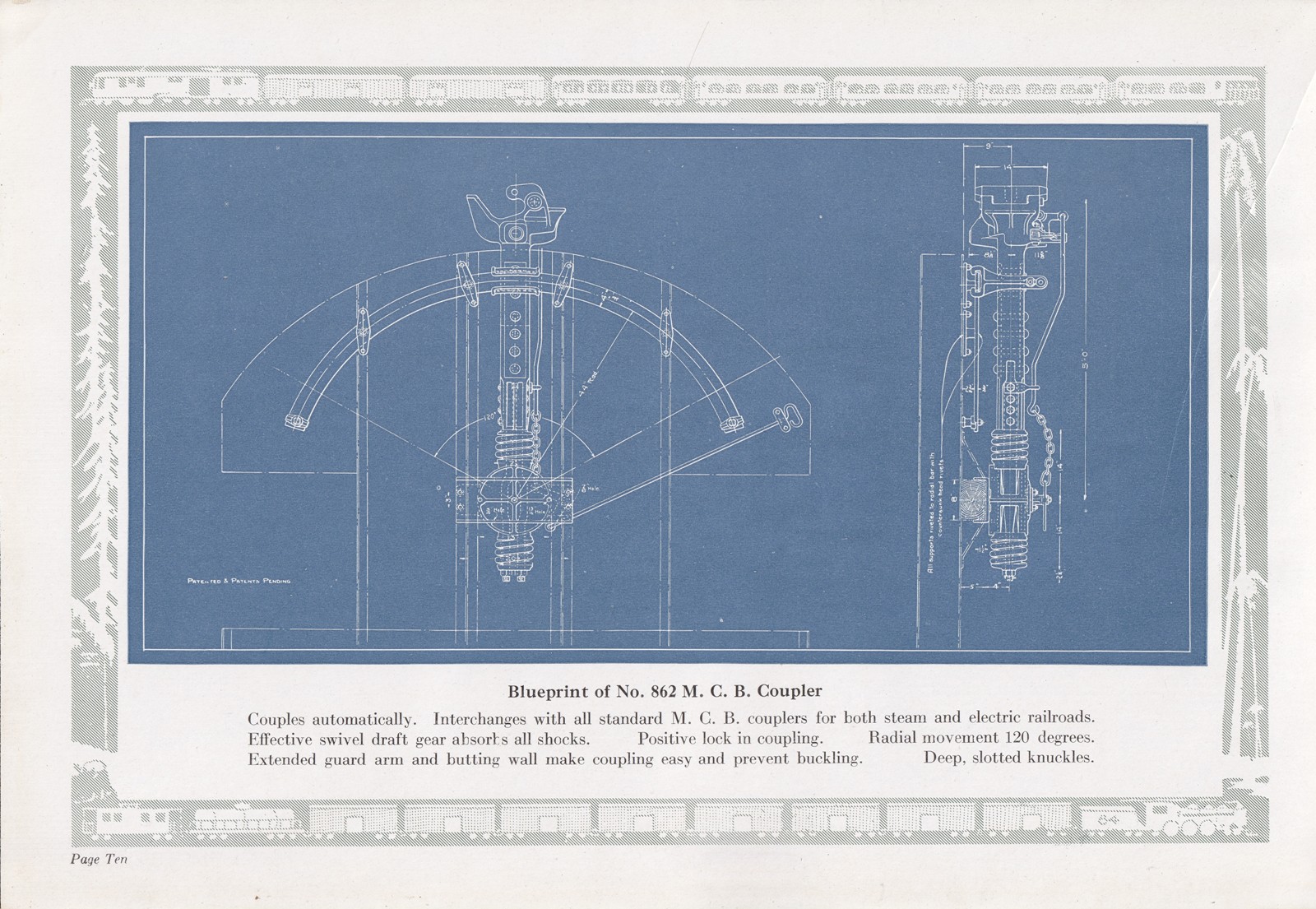
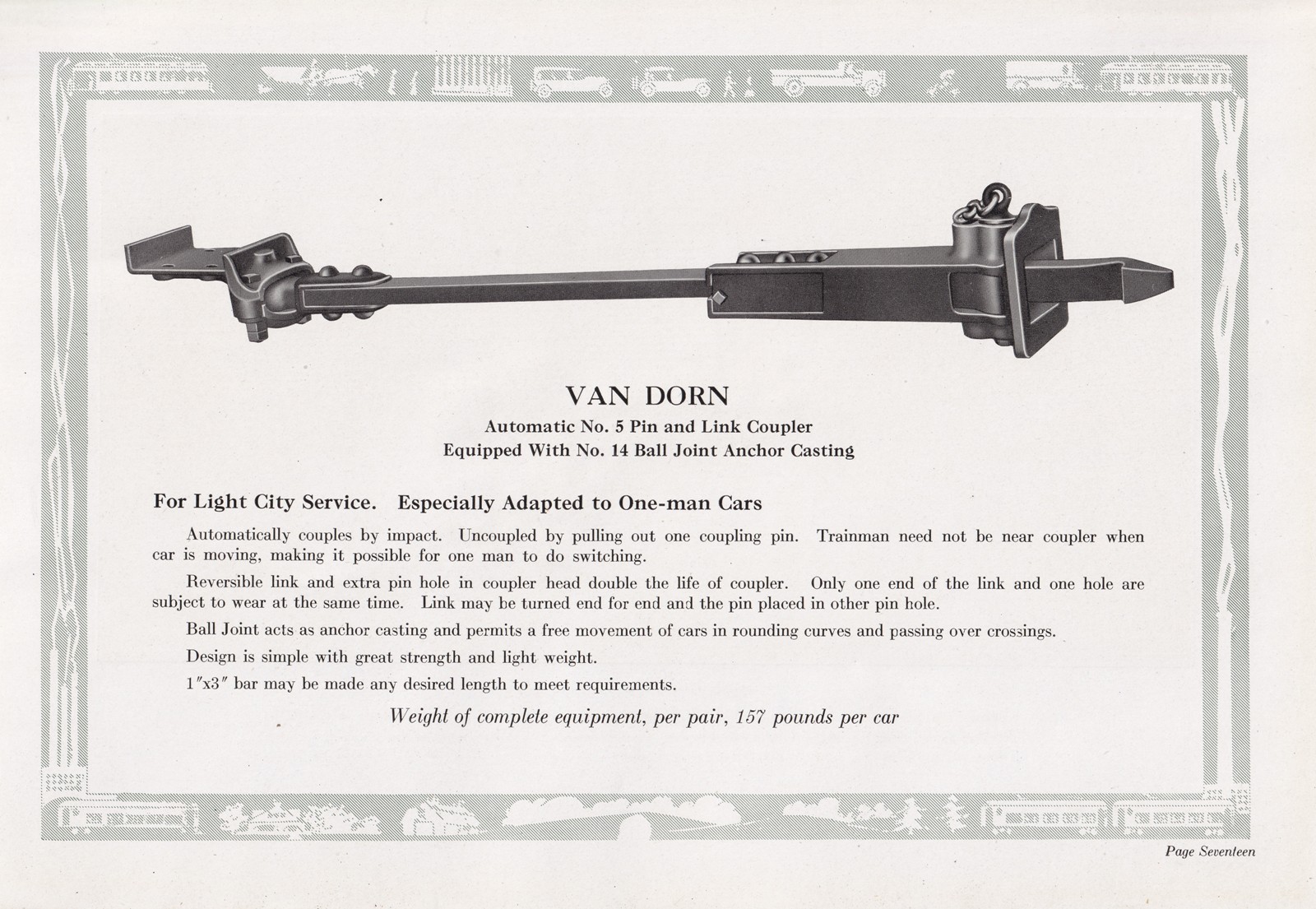
We'd like to extend our thanks to Jay Scott, who has donated a small stack of original Van Dorn coupler catalogs to the museum. Unfortunately, we don't know what year this was issued. Overall, it's a very interesting piece from the company's marketing department. Enjoy!






Thursday, December 29, 2022
On Target
A friend recently sent us an interesting picture, dated 1949. The main subject of the photo was obviously meant to be the New York Central streamliner leaving Chicago, but off to the right you can see a gondola with a Van Dorn target end. This seems much later than we might have thought for these ends to be in service. Who knew? But Van Dorn is one of our favorite subjects, so here you go.

Correction! Dennis Storzek points out that this is actually a Haskell & Barker design, not Van Dorn, since the ribs form a spiral and not concentric ovals. This is an interesting example of a company making a trivial change to somebody else's design in order to avoid proprietary or patented intellectual property, something that has happened quite often.
Friday, February 26, 2021
Even more Van Dorn couplers
Our friend Bill Wulfert continues to roam around the museum and gather photos of Van Dorn couplers in the museum's collection. This week's haul includes both link-and-pin and MCB types.


EDIT: Close inspection on Sunday revealed that the 1129 has a type 930 MCB coupler. An exploded-view illustration of this type was included among the donated Van Dorn materials but, intriguingly, the illustrated version looks somewhat different than what's on the car. Apparently they made changes to the casting at some point.

Saturday, February 13, 2021
More Van Dorn couplers
Bill Wulfert has sent in more photos and information about additional Van Dorn couplers at the museum. This time he was taking photos underneath recently-restored Northwestern Elevated car 1754 as well as more photos underneath our Metropolitan-West Side cars. He writes:
'L' car 1754 has Van Dorn #4A couplers. The one on the west end has not yet been painted.


Next is the drawbar mounting on the (west) motor end. It is quite compact. The coupler on the (east) end is the same. The cables for the Heat & Light" jumper and MU control are shown.


I also looked at the couplers on the 1797 and 1808, and they too are #4A's. Of course the North Side 'L' lines used Stearns & Ward couplers on their cars. The CTA swapped out the Stearns & Ward couplers, supposedly for use on the Plushie 'L' cars 4251-4455 that had Van Dorn couplers. Remember that the Lake St. and Metropolitan Plushies used Van Dorns. When looking at our Plushie cars, it does not seem possible to swap out the drawbars. Perhaps the 4A came off of other wooden cars that were being scrapped. I have not found any documentation on the swap to the 4000s However, we know that 1797 was at Wilson Ave. shop on September 20, 1954 for a coupler change out. A group of wooden cars had the change out between July and September of 1954. Most were in and out in one day, but 1796 was at Wilson for five days. Probably it was delayed by more pressing projects.
We've know about the coupler change
outs on the wooden cars, but have determined that the Plushie &
Baldies Stearns & Ward couplers are mounted totally different than
what is on the North Side wooden cars. Glenn Andersen mentioned that
the Lake St. and Met Plushies had Van Dorn couplers, and that made it
difficult to make up trains when all of the 4000s were sent over for
North-South service via the new subway. All of the Baldies, including
those on the Met had Stearns & Ward couplers, and it appears that
most of the Baldies were assigned to Ravenswood - Englewood service
prior to the subway. In order to spread the 66 Baldy trailers out among
the Ravenswood - Englewood & Howard - Jackson Park trains, they had
to have Plushies with Stearns & Ward couplers. They supposedly did
NOT operate revenue trains with adapter couplers. So the solution was to
change out the couplers on the wooden cars, in order place the S&W
couplers on Plushies.
As
I mentioned earlier, I have not seen any work orders or bulletins about
putting the S&W couplers on the Plushies, but we have a shop list
that shows some of the wooden cars getting Van Dorns.
I also went back to the Met cars to look at how they are attached to the car body. With my trusting quartz light, I was able to get some good pictures.

The first one is the rear of the drawbar, which goes through a car body frame member. It has a short spring.

The next one is on the other side of the frame member, and again it has a small spring. I was not able to see any mill marks on the rail, such as weight or date of rolling. I did not venture down to the other drawbars to look at them.
Friday, February 5, 2021
Van Dorn automatic coupler equipment
Bill Wulfert reminded me that he had sent me photos a couple of months ago taken in the cab of our Broad Street subway car, the 55, showing the car's automatic coupler cutout switch. On the Broad Street cars, which used Van Dorn #2350 tight-lock couplers (more here), the air and electric connections were made automatically when the couplers locked but the motorman had to manually cut in the connections from the cab. Bill explains:
There is a cutting valve in each cab, and a "key" is inserted (it looks like a piece of steel with a notch in it) to uncouple cars. I'll have to look for that. But it also talks about closing the Westinghouse valve (which is just a standard WABCO brass angle cock under the coupler). That part never made sense to me, as either the couplers are automatic or they are not!
There is an air operated drum switch behind the coupler, and when you put the "cutting key" in the slot, and move the handle part way, you can hear the drum throw, which I'm sure is disconnecting the coupler buttons electrically. Then you can move the key a bit more, and turn the handle in the cab a bit more, and I believe those air buttons on the sides of the electrical contacts activate the pneumatic uncoupling mechanism.
I did try the cutting valve when we still had the 126. It did not have power, but I used the key in the 55, and it worked. The cars uncoupled, and there was no big rush of air, so the automatic equipment worked. Hopefully I can find those instructions for you.
You can also move the lever on the top of the coupler in order to manually uncouple cars, such as cars in the yard. I'm not sure if you have to throw anything else, as when the car is pumped up the air connections may not be closed.
Bill sent these photos of the cut valve or switch in the cab of the 55. The first two photos show the switch; then there are two photos of the switch with the handle inserted, in two different positions; and finally a photo of the handle.


Van Dorn made a variety of switches, contacts, junction boxes, valves, and other appurtenances that were related in some way to the operation of its automatic couplers. Very few examples of any of it are thought to still survive.
Subscribe to:
Posts (Atom)


