The invention that brought William T. Van Dorn fame and fortune, and the piece of equipment most closely associated with the name Van Dorn, was the automatic link-and-pin coupler. I'm not positive exactly when Van Dorn patented his first automatic link-and-pin design but it appears to have been the 1880s, a time when couplers were quickly becoming one of the aspects of railroading in most obvious need of improvement. Standard link-and-pin couplers were incredibly dangerous; the tenure of conductors and brakemen could generally be measured in fingers lost. Deaths from having to go between cars to make and break trains were common.
Van Dorn's invention, the automatic link-and-pin coupler, built on existing technology but sought to make it unnecessary to stand in between cars being coupled. Van Dorn couplers are described here, but briefly, the coupler head was designed so that a pin could be placed in one of two vertical holes and so that a spring on one side of the coupler head could apply sideways pressure to the link. The link itself was symmetrical, with a hole in the middle and a hook at each end. To couple two cars, a link was pinned into one coupler using the hole in the link, while in the other coupler (with no link), its pin was placed in an offset hole in the coupler head. When the cars were pushed together - without the need for anyone on the ground or near the coupler at all - the link hooked onto the pin in the other coupler, the spring built into the coupler head keeping it from unhooking.

This drawing showing how the coupler works is from patent 711549
This system was inferior to knuckle, or MCB, couplers for heavy freight service and by the mid-1890s MCB couplers (which Van Dorn also manufactured) were standard on steam railroads. But the Van Dorn link-and-pin coupler was lighter and easier to maintain than MCB couplers so it found favor with street railways, interurbans, and rapid transit lines. Van Dorn couplers were in use on the CA&E until 1957 and on the CTA, in work service, into the 1970s. Van Dorn itself offered a range of couplers, varying mainly in their size. There were also a variety of offerings for draft gear.
The following illustrations are among the original Van Dorn Coupler Company materials donated to the Illinois Railway Museum by Larry Larson. The images are the property of the Illinois Railway Museum and may not be reprinted without permission.
#4A Coupler
Here we have a #4A coupler with a #16 link and a #16 pin. There are quite a few illustrations in the donated Van Dorn materials of early link-and-pin style Van Dorn couplers, but unfortunately the biggest difference between them is often their size, and in the absence of any background their size is difficult to gauge.
Here's another #4A coupler, or coupler head, but this time it's paired with #104 draft gear.
This #4A coupler is fitted to #36 draft gear with a #36D anchor casting and a #1145 anchor. The two preceding images both show up in the
coupler catalog.
The Northwestern Elevated Railroad apparently used #4A couplers, as the ex-Northwestern 'L' cars at IRM including 1754, 1797, and 1808 all have this type. Photo by Bill Wulfert.
#5 Coupler
It appears that the #5 coupler was one of the smaller couplers made by Van Dorn. It was evidently recommended for streetcar use. That curved top to the coupler's buffer face is interesting. This illustration notes that the coupler has a #5 link and a #5 coupling pin.
Unfortunately this illustration took some damage, but it shows a #5 coupler head at the end of a reasonably long bar attached to a #14 ball joint (this image shows up in the
coupler catalog).
This is described as a #5 coupler head with a #5 link, #5 coupling pin, and a #14 ball joint. It even points out that a 1"x3" short bar is used for the shaft.
This is described as a #5-1/2 coupler. Van Dorn didn't limit itself to whole numbers in its coupler designations. We found a pair of drawings, one for a #5 coupler and one for a #5-1/2 coupler, and the only differences seem to be the size of the intended shaft and the height (not width) of the strike face on the coupler, which was higher on the #5-1/2 than on the #5. I suppose that the differences were slight enough that they didn't feel compelled to use an entirely new number.
#11 Coupler
Here we have a #11 coupler head with a #11 link and a #5 coupling pin.
This illustration is described as "#11 or 11-1/2" so perhaps the differences between those two types were very minimal. Or perhaps the person writing those notes on the photos a century ago just wasn't sure. Regardless, this one too has a #11 link and a #5 coupling pin according to the note.
This is an actual photograph, not an illustration, and it is described as a #11-1/2 coupler.
And this, apparently, is the illustrated version of the above photo. It's described as "#11 or 11-1/2" but since the photograph is described as a #11-1/2, and it looks very much like this was based off of the above photograph, I suppose it's a #11-1/2. The illustration also says that it has a #5 coupling pin (note that the pin may actually be different than what's in the above photo) and a #100 stop casting.
#16 Coupler
This is a #16 coupler head and is noted as having a #16 link and a #16 coupling pin. This type of coupler is a bit unique because I stumbled upon a description of when it was designed and for what purpose. In, 1901 Street Railway Review (
link here) published a brief article about Van Dorn designing the #16 (for motor cars) and #15 (for trailers) couplers specifically for use on the new Manhattan Railway elevated system electrification. There's also an illustration showing a drawbar of extravagant length connected all the way back to the car's body bolster. The #16 is also the type of Van Dorn coupler used by the CA&E on its wood cars, which makes sense given that when the CA&E first opened in 1902 its cars also used motors and control equipment that had been designed for the Manhattan Railway electrification project the year before.
#18 Coupler
Here's a #18 coupler head with a #16 link and #16 coupling pin. This style of coupler head was designed with a channel down the back of the coupler head suitable for mounting to a section of rail.
The #18 coupler is the type used on IRM's two Metropolitan-West Side Elevated cars, 2872 and 2888. This photo was taken by Bill Wulfert of the trailer end of the 2888 showing the car's coupler and the draft gear, which uses 80# rail. Photo by Bill Wulfert.
#19 Coupler
The #19 coupler shown here is fitted with a #19 link and a #1121 coupling pin. This coupler appears in a 1907 Street Railway Journal article (
link here) and is described as being the "latest type, embodying several new features." It can therefore be supposed that this type was developed around that time.
#20 Coupler
This isn't actually a #20 coupler; there aren't any illustrations of a #20 among the Van Dorn records we acquired. Rather, this is a #20-1/2 coupler head with a #19 link and a #17 coupling pin. It's also noted as having a "special carrier."
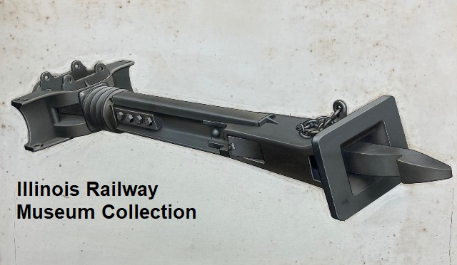
This setup looks bizarre, but it resembles the proposed mounting of the #16 couplers linked above and it was actually in the Van Dorn catalog. It's described as a #20-1/2 coupler head "with rail draft gear" (I guess that about covers it!). Sure enough, I came across a description of the original series of Hudson & Manhattan subway cars and they were described as having drawbars of "85-lb. bent rails with Van Dorn couplers."
#21 Coupler
This is a #21 coupler with #200 draft gear. The coupler head fits onto a section of rail used as the shank, and the following illustration shows a channel in the back of the coupler head for this purpose. This image shows up in the
coupler catalog)\.
This is described as a "#21 or 21-1/2" coupler head with a #11 link and a #5 coupling pin.
This is another "#21 or 21-1/2" coupler head. It's got a #11 link, a #5 coupling pin, a #200 swivel casting, and it uses 60-lb rail for the coupler shank.
#27 Coupler
Here's a #27 coupler head with a #11 link and a #5 coupling pin. I believe the #27 is the only Van Dorn coupler shown in the files with that "wishbone" looking design cast into the top.
Here's the same coupler from a different angle. Again, it's a #27 coupler head with a #11 link and a #5 coupling pin.
This #27 coupler is fitted to #332 draft gear. This image shows up in the
coupler catalog.
#29 Coupler
This is a #29 coupler head with a #11 link and a #5 coupling pin. This coupler head is apparently designed to fit onto a section of rail.
#37 Coupler
The highest-numbered link-and-pin coupler included in the materials that were donated is the #37, shown here with a #19 link and a #19 pin.
Other Hardware
It's obvious that Van Dorn didn't just make couplers; they also made draft gear and other associated components. Here we see a #11 ball joint on the left with a #515 anchor on the right.


No comments:
Post a Comment