The S-Motor
New York Central 115 and the Story of the New York Electric Zone
By Frank Hicks
Foreword
John Wisker was running late. As he opened the throttle of his steam engine and train 118 pulled away from the New York Central Railroad’s platform in White Plains, New York, he was already a minute and a half behind schedule. The 19-minute trip south toward Grand Central Station was delayed another five minutes at 110th Street to let a local from Croton proceed past. Wisker, an extra-board engineer with little experience in commuter service, was further agitated by his engine, which was having trouble keeping up air pressure in the brake system.
The January weather was foggy and dim, with snow in the air, as Wisker’s train descended into the Park Avenue Tunnel at 96th Street and sped southward toward the station at 42nd Street. In the tunnel, the darkness was exacerbated by the fog and by thick smoke from other trains speeding through the densely traveled passage. In the swirling smoke, barreling ahead at some 20 to 30mph, Wisker never saw the “stop” signals.
At 58th Street, just shy of the tunnel’s exit into an open cut, the markers of a stopped New Haven Railroad express from Danbury suddenly appeared out of the gloom straight ahead. There was no time even to slow down. Train 118’s engine tore through the rear car of the express, telescoping it to within six feet of its length. Of the 60 passengers who had boarded the last car of the Danbury express at New Rochelle, 15 were killed. It was – and to this day remains – the worst train wreck in Manhattan’s history.
A contemporary illustration shows rescuers working in the aftermath of the wreck.
The Park Avenue Tunnel wreck of January 8, 1902, made clear what was already understood by enginemen who frequented the route into Manhattan: the smoke-clogged approach to Grand Central Station was inadequate, overcrowded, and unsafe. Fixing these problems would take more than a decade, tens of millions of dollars, and technology that in some cases was just then being invented. The heart of the solution, though, was already in plain sight, gliding along 59th Street and rumbling overhead up Third Avenue: electric traction.
Headline Image: NYC 115 is southbound at 140th Street with a string of sleepers on June 7, 1958. New York Central System Historical Society Archive.
The Manhattan Terminal Challenge
Within a week of the Park Avenue Tunnel wreck, railroad president William Newman had announced that the New York Central (technically the New York Central & Hudson River, as full unification of the vast NYC System wouldn’t occur until 1912) would electrify the route into its Manhattan terminus. Before long, the city made it a necessity when an ordinance was passed banning the operation of steam locomotives on the main lines into Manhattan after July 1908. The NYC had already been contemplating electrification due to the extraordinary number of trains being funneled into and out of Grand Central Station – roughly 700 each day. As the suburbs north of Manhattan grew, traffic was only expected to increase.
Meeting the demand wouldn’t involve simply electrifying the existing tracks; it would require an entirely new terminal. The existing Grand Central Station was an expansion of the 1871 Grand Central Depot, including an annex three blocks north that had added badly needed platforms, but it was increasingly overwhelmed by traffic levels. The stub-end design of the terminal also increased switching requirements.
The north end of Grand Central Station at the turn of the century showed off its grade-level platforms and ornately decorated train shed.
The NYC created a formal Electric Traction Commission to study the problem and develop solutions. The chairman was NYC Chief Engineer (and soon-to-be-Vice President) William Wilgus, an innovative and capable man. Members included Frank Sprague, who had designed the first successful street railway electrification in Richmond, Virginia, in 1888, as well as the first successful application of multiple-unit (MU) operation a decade later in Chicago; Bion Arnold, an electrical engineer from Chicago; George Gibbs, an engineer and consultant who was also working with the Interborough Rapid Transit system around this time to design a new generation of all-steel subway cars; John Deems, general superintendent of NYC motive power; Edwin Katte, who was in charge of actual electrification work for the NYC; and several others.
William J. Wilgus (left) and Frank J. Sprague
On March 19, 1903, Wilgus presented his plan to NYC management for the new Manhattan terminal, to be known as Grand Central Terminal (GCT). The new terminal would replace the existing station at 42nd Street with a complex that at once vastly increased the number of platforms while reducing the amount of real estate needed. The solution, made possible by electrification, involved two levels of subterranean terminal tracks – one level for express trains and another for commuter trains – as well as turning loops to ease switching challenges. The notorious Park Avenue Tunnel would be extended south all the way to the terminal, with electrification to points north of the Harlem River permitting safe operation in the lengthened tunnel as well as the removal of the smoke vents that lined the median of Park Avenue.
The stupendous cost of the project would be borne in large part by the sale of real estate and “air rights,” one of the first applications of that concept. With the sizable surface-level railroad yards between 42nd and 50th Streets covered over, their tracks moved underground, and the footprint of the yards compressed by using two levels for the new terminal’s platforms, the sale of real estate among the most valuable in the country would finance the improvements. Wilgus’s plan was accepted in June and bids were solicited from four firms to design the terminal, with the firm of Reed and Stem (owned in part by Wilgus’s brother-in-law, Charles Reed) being awarded the contract. But while the architects focused on how to build the world’s greatest, most beautiful, and most efficient railroad terminal, it was up to the engineers to make the electrified railroad beneath its floors work.

A track plan of the subterranean express level planned for Grand Central Terminal shows dozens of stub-end tracks and a turning loop underneath the concourse and waiting room.
Main Line Electrification
Although the terminal project itself only required electric traction as far north as Mott Haven Yard, the NYC’s large coach yard just north of the Harlem River in the Bronx, the benefits of a more extensive electrification project were clear. If suburban lines could be converted to entirely electric operation, commuter trains could avoid time-consuming motive power changes on each trip. Furthermore, the use of electric MU cars would vastly simplify the switching challenges at the terminal by enabling trains to simply operate in reverse out of their stub-end tracks without having to be turned. As such, the NYC decided on electrifying the 24 miles of the route to White Plains North, on the Harlem Division, and the 34-mile line to Croton, on the Hudson Division.
The engineering challenge was enormous. Only one steam railroad had previously electrified a section of its main line. In 1895, the Baltimore & Ohio had opened a new route directly through downtown Baltimore. The route used a 1.5-mile long tunnel under Howard Street to traverse the center of the city, and with a 0.8 percent grade throughout the tunnel’s length, steam power was out of the question. General Electric (GE) had been tapped to design a pioneering system to solve the problem.
What GE developed was a system powered by 600V DC, similar to the street railway systems popping up around the country at the time. Rather than trolley wire, it used an overhead trough created by Z-channels for power distribution, though this was later replaced by a third-rail system. The locomotives were unlike anything seen before. Each locomotive used two permanently joined, two-axle units and a steeplecab design. The four axles each carried a 360HP motor mounted on a sleeve, or quill, around the axle that drove the wheels via rubber pads. The locomotives used what was effectively a giant K-controller in the center of the cab for control and could be double-headed but not run in MU.
One of the distinctive two-unit locomotives from the 1895 B&O electrification
When the NYC looked to electrify its routes out of Manhattan, it turned to GE, the only one of the two major electrical equipment manufacturers (the other being Westinghouse) with experience in main line electrification. Electric railway technology had progressed significantly in the eight years since the B&O electrification, though – and the NYC project would need those advancements. GE recommended a 600V DC system with third-rail power collection, similar to the rebuilt B&O electrification as well as recent railway projects like the Manhattan Railway elevated system and the Aurora Elgin & Chicago high-speed interurban line in Chicago. Contracts were awarded to GE in late 1903 for electric generating equipment, power distribution equipment, and of course motive power and equipment for self-propelled cars.
The MU cars were the simple part of the equation. They were, in essence, larger and heavier versions of the Manhattan Railway’s electric MU elevated cars. The MU cars carried two GE 69C 200HP motors in a single truck while the other truck was a trailer. They were fitted with Type M electromagnetic-contactor MU control, a variant of the Type M system developed in 1900 by Sprague and GE for the Manhattan Railway electrification. The cars were 62’ long and of all-steel construction. The NYC ordered 180 cars, 125 motor cars and 55 trailers, to hold down suburban service to White Plains and Croton.
The NYC’s MU electric cars were among the earliest railroad passenger cars built entirely out of steel. Street Railway Journal.
The thornier challenge, perhaps, was designing an electric locomotive that could meet all the NYC’s needs. The B&O locomotives, besides simply being outdated, weren’t up to the task. They couldn’t be run in MU, were too slow for the longer distances and high-speed service sought by the NYC, and weren’t powerful enough to haul the all-steel passenger trains that were already on the horizon for the railroad. Something altogether novel was needed.
A New Type of Locomotive
The Electric Traction Commission worked from December 1902 to May 1903 on developing specifications and requirements for an electric locomotive design, and bids were requested from a total of 10 manufacturers, half foreign. Bids were opened in October 1903 and the following month the contract to design the locomotives for the NYC electrification was awarded to GE.
The contract was given to GE on the understanding that the firm would work with the American Locomotive Company (Alco), also located in Schenectady, to develop the mechanical aspects of the design. Leading the effort on behalf of GE were W.R. Potter, Engineer of the Railway Department, and Asa F. Batchelder, while Alco’s representation was led by William Dalton and H.B. Hunt.
The record suggests that Batchelder was responsible for the basic design of the locomotive. His concept, which he patented in an application filed in November 1903, was ingenious. The locomotive would need extremely powerful motors to pull heavy passenger trains at speed, but at the time, motors this powerful were difficult to fit into locomotive frames in typical nose-hung street railway fashion. One solution was to build the motor armature around the driving axles to make the most of the space under the locomotive. The B&O steeplecabs of 1895 had done this with motors mounted around the axle on a sleeve, or quill. Batchelder’s design was different: the locomotive’s driving axles would carry the motor armatures directly in an arrangement that would come to be known as a “bi-polar” setup.
Batchelder’s locomotive would run on four drive axles, each with a standard DC motor armature formed around the axle. All four commutators were on the same side of the locomotive. Each armature was flanked by two large pole pieces (hence the “bi-polar” name), with the next motor’s pole piece just inches away on the opposite side of a frame cross-member. The main frames running the length of the locomotive outboard of the wheels, together with the heavy cross-members and buffer beams at the ends of the frame, formed the field magnet structure. The entire locomotive frame served as part of the motor circuit. Furthermore, the design totally eliminated gearing, saving an estimated 3-5% in efficiency.
Asa Batchelder’s patent for the electric locomotive design that would become the S-motor shows how the magnetic circuit went right to left through the motor pole pieces (14) and armatures (16), returning through the locomotive side frames (1 and 2). US Patent Office.
Batchelder’s design anticipated the vagaries of railway service, too. Normally, the intermediate cross-members were not in the circuit because the magnetic flux would extend directly from one pole piece to the next one in line. But if there were variations in current between motors, the difference in load would find a path via one of the intermediate cross-members, creating a “local” magnetic circuit in addition to the primary circuit. Additionally, the need to service or replace motor armatures was anticipated in the design of the pole pieces. They were essentially vertical, rather than formed to the curvature of the motor, to allow the axle and armature to be dropped straight down from the locomotive for replacement.
Some voiced concerns with the design. No electric locomotive since the diminutive Central London tube locomotives of the 1880s had been built with armatures mounted to the axles in this way, and those locomotives had been notoriously hard on the track. But the Central London locomotives had mounted the entire motor to the axle, not just the armature. Batchelder’s system, with the pole pieces attached to the locomotive frame, minimized the “dead weight” on the axles by adding only the 11,000-pound armatures as unsprung weight rather than the entire motor assembly.
This 1904 illustration of one of the S-motor’s wheel/axle/motor arrangements shows (left to right) the journal box; the yokes reaching over the wheel to support the brush holders; the motor commutator; the motor armature with the pole pieces above and below; the other wheel; and the other journal. Street Railway Journal.
Batchelder’s 1903 patent was illustrated with drawings of a four-axle boxcab, but such a locomotive wouldn’t be suitable for the high speeds anticipated for the NYC operation. Some sort of lead truck arrangement would be necessary to guide the locomotive into curves and prevent hunting, or “nosing,” at speed. Since the locomotive was intended to be double-ended, to maximize operating flexibility, the wheel arrangement would need to be symmetrical. The obvious solution seemed to be adding a single lead axle to each end, making the locomotive in effect a Mikado, a wheel arrangement just then gaining popularity following an 1897 order for 2-8-2 steam engines from the Nippon Railway of Japan.
For the new NYC locomotive, Batchelder’s four-axle bi-polar design would be put into practice by mounting 550-horsepower motors on four drive axles with 44-inch wheels. Single-axle pony trucks mounted to the frame on radius bars, with the ends of the frame riding on swing links, were added to both ends for stability at speed. The rigid wheelbase was 13 feet, with an overall wheelbase of 27 feet.
By June 1904, the locomotive’s wheel arrangement and bi-polar motor configuration had been settled, but the design of the body wasn’t finalized. This illustration shows a covered central corridor, as the final design had, but with a far smaller cab and sloped, steeplecab-style hoods. Street Railway Journal.
The next question involved the style of superstructure. The style chosen was unique: something like a cross between a steeplecab (like the 1895 B&O locomotives and a few street railway locomotives built by GE) and a boxcab, the NYC locomotive was fitted with a large central cab that was just shy of half the locomotive’s overall length. At either end was a full-width hood, which in the original design sloped down toward the end of the locomotive in a steeplecab configuration. Down the center was an enclosed, full-height corridor to provide a protected walkway from one end of the locomotive to the other. At some point prior to construction, though, the sloped hoods flanking the corridor were changed from sloped to squared off, forming constant-height “shoulders” for the central corridor all the way to the end of the locomotive. The GE engineers couldn’t know it at the time, but the unmistakable and unique stepped ends of the locomotive would be replicated tens of thousands of times over in model form over the coming decades.

The final design for the first NYC electric locomotive is shown, with the motors depicted as a cutaway view. Street Railway Journal.
Under the full-width hoods of the locomotive, flanking the central corridor, was placed the majority of the electrical equipment. On the floor lining the corridor were the resistance grids. Over them was mounted the equipment for the GE Type M control system. Heavy DB-151B1 type contactors carried the motor current loads, while acceleration was handled through a high-voltage GE controller. For low speeds, all four motors were connected in series; then in two pairs of parallel motors for mid-speed series-parallel operation; and all four motors were connected in parallel for higher speeds. The controller used a lock magnet feature to prevent the throttle from being advanced if motor current were too high, thereby preventing unduly rapid acceleration from damaging the motors.

Under the hood “hips” at either end of the locomotive were banks of electromagnetic contactors, as shown, with resistance grids located in steel boxes that were vented to the outside. New York Central System Historical Society Archive.
The spacious cab contained two engineer’s positions at opposite corners, each with a master controller and K-12 brake stand; a large electrically driven air compressor; and an oil-fired 80 PSI steam boiler for heating coaches. The cab had exterior access doors in the center of each side and entries to the corridors through the ends of the locomotive.
One of many unusual features of the locomotive was its methods of current collection. Although the vast majority of street railways and interurban lines used overhead wires, conventional wisdom at the time suggested that this system was unsuitable for the high currents demanded by mainline electrifications. Moreover, extremely low clearances in the Park Avenue Tunnel – sometimes as little as 4 inches over car roofs – made overhead wire a difficult proposition. The alternative was third rail, which had been adopted by the B&O electrification and was in use by a variety of interurban lines and rapid transit systems, including the Manhattan Railway. The NYC locomotives would be fitted with third rail shoes, actually protruding paddles mounted in pairs, at each corner of the locomotive. Each shoe, or paddle, had its own sizable fuse box.

The roomy cab of the locomotive contained an engineer’s station for each direction, visible at right; the CP-19B air compressor pictured; and an oil-fired boiler to heat passenger cars, which was not installed when this photo was taken. Street Railway Journal.
But at less than 39 feet overall, these locomotives were shorter than some of the gaps that would be necessary to accommodate switches and crossovers needed for the complicated trackwork in the subterranean GCT approaches. The risk of a locomotive getting “stranded” beyond the reach of the third rail was high, and so a backup system for electrical pickup was added. Small pantographs that could be raised or lowered pneumatically were mounted atop the corridor roofs just past each end of the locomotive cab. In the GCT approaches, third rail sections were hung from the ceiling over switches and crossovers, enabling the locomotive’s pantographs to pick up power through those gaps.
The locomotive was also fitted with various standard accoutrements. Large electric headlights sat atop the ends, an air whistle behind one and a bell behind the other. Boiler-tube pilots protected the pilot trucks, and the end beams featured buffers for passenger car diaphragms, poling pockets, and small wheels that could be turned to pull uncoupling chains. MU sockets on the ends enabled operation of two or three locomotives together. The prototype of this novel design, known as a 1-D-1 in traction parlance to denote single unpowered axles flanking four powered axles, was constructed during the summer and fall of 1904. By the end of October, the GE engineers in Schenectady had completed assembly.
Number 6000
The prototype locomotive, number 6000, cut a striking profile. When new, it was prominently lettered for the New York Central & Hudson River. The pantographs were mounted higher than was planned for the actual electrification in New York City. Krambles-Peterson Archive.
The prototype electric locomotive, New York Central & Hudson River 6000, first ran on October 27th, 1904, and made its public debut on November 12th. The NYC had taken one of its tracks between Schenectady and Amsterdam, New York, out of service for a length of six miles and had converted it into a test track for the new electric locomotive. Third rail was laid alongside the track and short sections of demonstration overhead, heavy and rigid enough that it was more properly considered rail than wire, were erected to simulate the third-rail gaps at switches and crossovers in the tunnels. (This was mounted higher than was planned for the tunnels, so for use on the test track, the locomotive’s pantographs were raised up atop pedestals.) More than one onlooker noted that the test track was located at nearly the exact same spot as the DeWitt Clinton locomotive trials 70 years earlier.
The exhibition on November 12th saw the Electric Traction Commission host a sizable contingent of guests from manufacturers, railroads, and the press. Engineers and executives from the Pennsylvania Railroad and the New Haven, both of which were in the earlier stages of planning their own electrification projects to serve New York City, were there, as were men from various steam railroads, interurban lines, and street railways. Sizable contingents from the NYC, Alco, and GE were there, of course. Even George Westinghouse was present.
Number 6000 made its debut on November 12, 1904, pulling a train of distinguished guests along the test track near Schenectady. Street Railway Journal.
Number 6000 made trips with its demonstration train in the morning and afternoon. It raced the regular Fast Mail that left Schenectady just after noon, outpacing the steam-powered regular train until running out of electrified track. The NYC had ordered that the new electric locomotives must pull 550-ton trains, and number 6000 had no trouble with its seven-car, 480-ton train.
After the exhibition, the NYC, Alco, and GE engineers got down to the business of rigorously testing the prototype locomotive. NYC dynamometer car X2501 was brought in and various combinations of coaches and other passenger cars were used to test the locomotive’s performance under various conditions. The top speed reached by number 6000 was 85mph, attained on May 1, 1905, when it was running light. During another test on September 7, 1905, the locomotive was able to accelerate an 11-car train up to 80mph in just two minutes. It regularly raced NYC steam trains on the adjacent “Water Level Route” main line, and was also paced by steam-powered inspection locomotives on an adjacent track so engineers could observe running gear action from alongside. In late April, number 6000 faced off against a new K-class 4-6-2 Pacific, regularly beating the steam engine in acceleration and speed tests.
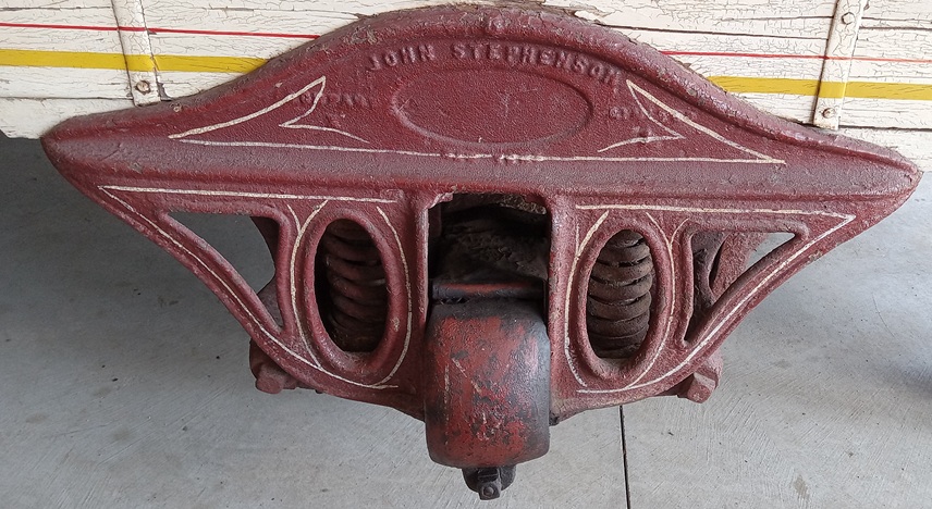
The tests went on for over two years and the electric locomotive racked up nearly 70,000 miles. The biggest change made to the design during the course of testing wasn’t to the locomotive so much as it was to the right-of-way. The tests began by using overrunning third rail similar to what was already in use on the Manhattan Railway and interurban lines like the Aurora Elgin & Chicago and Scioto Valley Traction. The contact shoes, or paddles, carried by 6000 were sprung downward. But winter conditions in the Mohawk Valley revealed problems with this arrangement, especially ice and sleet accumulation atop the third rail. This could make the contact shoes ride up over the ice, causing uneven power continuity or even power loss and threatening to damage equipment.
The Wilgus-Sprague underrunning third rail developed in 1905 used 70-pound bullhead contact rail held in a cast steel bracket with a wooden cover. Street Railway Journal.
The solution, attributed to William Wilgus and Frank Sprague with engineering support by Edward Katte, was an underrunning third rail. Cast mounts resembling an upside-down “L” held 70-pound bull-head contact rails from the top, with the contact paddles from the locomotive riding underneath the rail and contacting its downward-facing surface. Over the top of the rail, wooden boards provided protection – both for people on the right-of-way, who wouldn’t be electrocuted by stepping or falling on the third rail, and for the rail itself, which was protected from the worst of winter weather effects. Keeping the rail freer of snow and ice was also expected to help reduce current leakage and improve efficiency.
The Long Island Rail Road already used wooden boards over its third rail to improve safety, but it still used a top-contact design. To allow for potential interchange of trains, the NYC third rail contact surface was set at 2-3/4 inches above the running rail versus 3-1/2 inches above the running rail on the LIRR. With this standard, and the use of double-sided contact paddles with centering springs, the same contact shoes would enable operation on either system.
The original third rail beam setup is pictured, with twin “paddles” mounted to a short beam and two fuse boxes located over the beam. Later, the third rail beams would be moved out to the corners of the locomotive and one larger fuse box would replace the twin smaller fuse boxes. Street Railway Journal.
The changes made to the design between number 6000 and the first production unit were relatively minor. Extra framing beneath the journal boxes was removed; the locations of the poling pockets changed; smaller headlights replaced the oversized ones used on the prototype. One change that wasn’t visible but would attract attention later was the suspension arrangement of the single-axle pony trucks. Initially, the pony truck was mounted on radius bars and the end of the frame rode on swing links, but soon an alarming tendency to hunt, or “nose,” at speed was noticed. This was leading to the test locomotive widening the track gauge, with as much as 1-3/8 inches of gauge widening reported. The Electric Traction Commission began to study this in detail in December 1904. Alco and GE recommended a swivel truck, but the NYC’s experience with swivel trucks on 4-4-2 Atlantic locomotives had been that they exacerbated nosing. Between December 1904 and April 1905, tests were made of an alternative arrangement that substituted friction plates and side springs in place of the original swing links. The results were acceptable enough that new pony trucks designed from the start for friction plates and side springs were built in August 1905 and fitted to the locomotive.

Number 6000 is on the Schenectady test track with the NYC’s dynamometer car and 10 coaches. Street Railway Journal.
The issues continued, though. In February 1906, it was found that the spring hangers were hitting the underside of the locomotive cab and the nosing issue was still in evidence. More changes were made in the spring of 1906, including heavier centering springs, and the results satisfied the members of the committee. Even before this final fine-tuning of the design, the overall results of the tests on the Schenectady test track had convinced the NYC of the virtues of the 1-D-1 locomotive’s novel design. On May 2nd, 1905, following nearly 40,000 miles worth of testing by number 6000, the Electric Traction Commission unanimously approved the construction of an initial order of 34 locomotives built to essentially the same design as number 6000. The new electrics would be placed in a new locomotive class: class T.
Beneath the Streets of Manhattan
The first electric locomotives delivered to the NYC electric zone arrived lettered for New York Central Lines with NYC&HR sublettering. Library of Congress.
The first electric locomotives to run in the “electric zone” in New York City itself arrived at the instruction track between Morris Heights and Marble Hill in the Bronx on July 20th, 1906. Number 6000 was still in Schenectady at the test track during this period, so the first two production locomotives became the earliest arrivals at their permanent home. The production locomotives were assigned class T-2 and numbered from 3401 to 3434 (number 6000, soon to become number 3400, was the sole T-1 class locomotive). They were painted black and lettered “New York Central Lines” with “NYC&HR” in smaller lettering.
In the summer of 1906, the approaches to Grand Central Station were a beehive of activity as the yards, platforms, and approaches were subsumed into the new Grand Central Terminal complex. The third rail – what GE called the Wilgus-Sprague underrunning third rail system – was extended south through the Park Avenue Tunnel into Grand Central Station in September. On September 30, 1906, locomotive 3405 pulled a test train into the terminal, marking the very first electric operation into Grand Central.
In October 1906, the approaches to Grand Central Station were a sea of construction activity. Street Railway Journal.
During the autumn of 1906, the electrification was completed from Grand Central Station through Manhattan and over the Harlem River. On December 12th, the NYC began running trains of MU cars between the terminal and Highbridge in the Bronx, just a mile or so past the Mott Haven coach yards along the Hudson Line. On January 29th, 1907, MU car operation along the Harlem Line commenced as far as Wakefield, at the northern edge of the Bronx. A few weeks later, service on the Harlem Line was extended roughly another mile to Mt. Vernon.
By this time, the grand reconstruction project to replace Grand Central Station with GCT was in full swing. The work was made immensely more difficult, though, by the need to continue accommodating without interruption the 700+ trains each day that ran in and out of Grand Central Station. Construction on the yards and approaches began in June 1903. In 1904, the NYC purchased the adjacent Grand Central Palace, an exhibition hall located on Lexington Avenue, and converted its basement into a temporary terminal to provide extra platforms during construction. Additional land along Lexington Avenue was purchased to construct the two-level subterranean GCT yards and some 200 buildings were demolished during 1904 and 1905.
The location is uncertain, but locomotives 3405 and 3406 are shown coupled to an MU car during testing in the electric zone in late 1906. Street Railway Journal.
The NYC was also building infrastructure at the far ends of the electrified zone. It purchased a plot of land at the neck of Croton Point, along the Hudson, at one of the few spots with enough land between the Hudson River and the bluffs to build a yard. This became the site of Harmon Yard, named after the previous landowner, which provided a location to switch between steam and electric power. The NYC built a shop complex, Harmon Shops, to provide servicing and heavy maintenance to the fleet of electric locomotives and MU cars. There was a roundhouse, too, for the steam engines coming in from the north. A smaller shop, mostly for running maintenance of MU cars, was constructed at White Plains.
Concurrently with the progress on GCT and the NYC electrification, two other railroads were following closely in the Central’s footsteps and electrifying their approaches into Manhattan. The first was the New York New Haven & Hartford, or simply the New Haven, which like the NYC operated into Grand Central Station. Subject to the same problems and obliged to partner with the NYC on the solution of electrification, the New Haven struck out on its own in a couple of major ways. First, it elected to embark on a more ambitious electrification project: rather than just electrify 20 or 30 miles out of Manhattan, they would electrify their entire mainline as far as New Haven, Connecticut. From the point where the New Haven main line diverged from NYC tracks at Woodlawn, just north of the Bronx, to New Haven was more than 60 miles. The second difference was that rather than use 600V DC third rail, the New Haven would use a new and somewhat unproven technology: high-voltage AC transmitted through overhead wires.
This system, developed by Westinghouse, delivered 11,000V AC via overhead wires. This enabled a new power station built at Cos Cob, near Greenwich, Connecticut, to feed power directly into the overhead without rectifying it through a network of substations. The locomotives also had to function on 600V DC, though, since they used NYC tracks for the final dozen miles into Grand Central. As such, the first New Haven electric locomotives that Baldwin-Westinghouse debuted in late 1905 used series commutator motors capable of running on either AC or DC. The locomotives also received an array of current collection devices including third rail shoes and a small pantograph for DC current as well as large pantographs designed for more typical overhead wire that would collect 11,000V AC once the locomotives reached New Haven rails.

The New Haven EP-1 design was originally for a B-B boxcab, as shown, but pony axles were later added to change it to a 1B-B1 wheel arrangement. The locomotive has third rail shoes, a small 600V DC pantograph for use at GCT, and large AC pantographs for use on New Haven rails. ETH Library Zurich Image Archive.
The New Haven locomotives, designated EP-1s, were unremarkable-looking boxes with a pair of two-axle trucks. The motors were mounted around the axle on quills in an arrangement essentially identical to what the 1895 B&O electric locomotives had used. Testing at speeds up to 90mph revealed, however, a noticeable tendency of the locomotives to hunt. Before long, the B-B locomotives were fitted with pony axles on the outboard ends of their trucks, turning them into 1B-B1 locomotives.
The other railroad with an electrification project underway was the Pennsylvania Railroad (PRR), a newcomer to Manhattan. It had embarked on an enormous project to drive twin rail tunnels under the Hudson from New Jersey into Manhattan and then continue them under the East River to Queens. Tunneling work began in early 1905 and the Hudson tunnels were joined in late 1906. The tunnels under the East River wouldn’t be complete until 1908.
In the meantime, the PRR was building an imposing, steel-framed passenger station just a mile west of Grand Central Station. This new Penn Station was designed for trains to run through on their way to a yard in Queens, so it avoided the need for the massive underground stub-end yards required at GCT. Construction on the station began in May 1904. To operate trains from New Jersey to Queens, the PRR selected roughly the same type of electrification as the NYC: a 600V DC system using third rail. The biggest differences were in the length – about 10 miles for the PRR, versus some 40 electrified route miles on the NYC – and the fact that the PRR locomotives would have to do far less switching than their NYC counterparts and could be designed more as speedsters.
In 1907 a series of tests was carried out on the electrified Long Island Rail Road to try different locomotive designs. A pair of double-truck (B-B) locomotives pulled well, but as with the New Haven locomotives, they hunted badly at speed. A third test locomotive with four large-diameter driving wheels and a four-wheel lead truck – effectively the same wheel arrangement as a 4-4-0 steam engine – performed far better at speed, and its high center of gravity helped, rather than hurt, its stability.
The unusual look of the PRR DD-1 is shown off in this 1910 builder’s photo. Given the generally similar design requirements, the DD-1 and the NYC S-motor could scarcely have been more different. Krambles-Peterson Archive.
The PRR was convinced: they ended up ordering more than 30 class DD-1 locomotives, each comprising a 2-B+B-2 unit with two frames. Each frame carried an enormous 2,000hp traction motor with an armature some 5 feet in diameter that drove a jackshaft connected to the drive axles by heavy connecting rods typical of steam locomotive practice. The DD-1 had remarkably little in common with its NYC counterpart but also ended up a highly successful design.
On September 30, 1906, a train entered Grand Central Station under electric power for the very first time. Locomotive 3405 did the honors. Krambles-Peterson Archive.
After the first two NYC class T locomotives, or motors as the steam railroad called them, arrived in the electric zone in July 1906, the remaining 32 production locomotives were delivered between September and November. All were confined to testing and training while the third rail was extended and other infrastructure put into place to support their operation. Following successful introduction of MU car service to Highbridge and then to Wakefield, the NYC was ready to introduce its innovative new locomotives. In early February 1907, electric locomotives started hauling regular service trains from Grand Central Station to the northern limits of the electric zone, which at the time was Highbridge on the Hudson line and Mt. Vernon on the Harlem line. The NYC had successfully implemented its mainline electrification project more than a year ahead of the schedule imposed by the city’s ordinance. The exultation, though, would be short-lived.
New York Central 3415, the locomotive that one day would end up preserved at the Illinois Railway Museum, is shown in an October 1906 builder’s photo. New York Central System Historical Society Archive.
Woodlawn
On the evening of Saturday, February 16, 1907, the Brewster Express pulled out of Grand Central Station, its two class T motors humming at the head of a five-car train that threaded its way through the massive construction site. The train was a new high-speed service to White Plains introduced just the day before. It crossed the Harlem River and passed the Mott Haven coach yards on its way up the Harlem line, accelerating to a speed that struck even the passengers as excessive. On a curve at Woodlawn, in the north Bronx, the last car derailed. As the momentum of the locomotives continued to propel the train ahead, the derailed car dragged the cars in front of it off the tracks – all but the first car behind the locomotives – and then turned onto its side. The car was shredded as it was dragged at speed along the right-of-way, its contents spilling out as it went. The stricken train gradually slowed and stopped, the locomotives undamaged and still on the rails, except for the trailing idler axle of each. A gruesome trail of wreckage – both machine and human – stretched from 204th Street more than 1,000 feet north to 207th Street.
The Woodlawn wreck killed 24 people, mostly women and children who were in the last car, and injured more than 70 more. It immediately cast a shadow over the NYC electrification project, which itself had been triggered by a wreck with a lower death toll than the one in Woodlawn. It was clear that the cause of the wreck needed to be determined. Investigators examined three aspects: the train’s speed, the right-of-way, and the locomotives.
While it was concluded that the train’s speed was undoubtedly a major factor, it also seemed that this alone shouldn’t have caused the wreck. The tracks at the Woodlawn curve were super-elevated to permit high-speed operation, though it was theorized that the train in question had exceeded the design speed. The locomotives had been successfully tested on the Schenectady test track up to 85mph, which was faster than the Brewster Express had been going. As for the right-of-way, the 100-pound rails were among the heaviest on the NYC system at the time and were only a year old. The ties and ballast were also said to be in excellent shape. That left the brand-new T-class electric locomotives.
The discovery near the initial derailment site at 205th Street of spikes that had been sheared off, spreading the rails, focused attention on the lateral forces exerted by the electric locomotives at speed. During testing, a tendency to “nose” or hunt had been identified as a serious concern and had resulted in a major redesign of the single-axle pony truck. Testing in Schenectady suggested this had fixed the problem – but had it?
A new round of tests was conducted just weeks after the Woodlawn wreck, looking specifically at the lateral forces the electric locomotives were placing on the rails. As a control, a 4-4-2 steam engine typical of the ones being replaced in service to White Plains was also tested. Special attention was paid to the amount of force necessary to shear off spikes on the outside rail of the curve, where the highest forces were at play, which could lead to a derailment like the one at Woodlawn.
Exhaustive tests were done on the T-class electric locomotives following the Woodlawn wreck, recording a variety of measurements. Street Railway Journal.
The results were surprising. While lateral pressure against the rail was measured to be higher for the steam locomotive than the electric, the shear force on the spikes – a factor of lateral pressure offset by downward force on the rail, which increased friction against the tie plate – was the reverse. The electric locomotive’s lower center of gravity, with much of its mass in the frames and motors, meant more of its weight was forced laterally against the rail. A higher center of gravity such as on the steam engine acted as an inverted pendulum and reduced these forces. Moreover, the weight of the electric locomotive was more evenly spread out across a larger number of wheels, reducing downward force and increasing shear force on the spikes. At speeds up to about 40mph, the lateral forces exerted by the pilot truck axles actually exceeded those of the drive axles. Less weight on the pilot truck translated to greater shear forces exerted by those wheels. The maximum shear force at 60mph on a 3-degree super-elevated curve was calculated at 5,820 lbs. for the class T motor and 4,890 lbs. for the 4-4-0 steam engine. Both were within the shearing resistance for the spikes, generally between 15,000 and 17,000 lbs., and when those forces were spread across adjacent spikes, there was an acceptable safety factor of about six.
The investigation performed by the NYC engineers was inconclusive as to a single cause of the accident. The curve was designed for about 45mph, and evidence suggested the train had been exceeding that speed. This, combined with a hunting tendency to place lateral forces on the rails, could have combined with hidden track or component defects to make the electric locomotives spread the rails and cause the derailment. But this conclusion was far from unanimous. William Wilgus, whose team had developed the class T locomotive, vehemently disagreed that the locomotive’s design had played a part at all. He argued that extensive testing and design changes had solved the locomotive’s hunting problems – that the cause of the derailment was excessive speed, the fault of the engineer, and a localized defect at the point of the derailment.

This (obviously exaggerated) view of the locomotive going through an 1,860-foot radius curve measured friction resistance, force against the rail, spike shear force, and more. The general way in which the single-axle pony trucks were mounted to the frame is evident. Street Railway Journal.
Wilgus argued his position to NYC President William Newman and Senior Vice President William Brown. They were unconvinced, and testified to the New York State Railroad Commission that the likely cause of the wreck was the design of the new locomotives. In response, Wilgus wrote a report in April claiming that the cause of the accident was due to the weight of the locomotives spreading the rails – a suggestion that threatened both to subject the NYC to added liability, for placing new locomotives into service with insufficient testing and inadequate infrastructure, and to open Newman and Brown to charges of perjury for their testimony to the Railroad Commission.
NYC lawyers met with Newman, Brown, and Wilgus, and apprised them of the risk attendant to the report being made public. All agreed to burn their copies of the Wilgus report. However, this didn’t mean Wilgus had won. Without consulting him, Brown arranged for the NYC to proceed on the assumption that the design of the class T motors had, in fact, played a major role in the derailment. To reduce the hunting tendency at speed, the engineers recommended replacing the single-axle pony truck with a two-axle truck at each end of the locomotive. While work began on testing and implementing this change, an infuriated Wilgus recreated the report but kept it in his personal files. He resigned from the NYC in September, 1907.
There were no subsequent tracking or hunting issues with the class T motors. In 1908 and 1909, all 35 locomotives in the class had their single-axle pilot trucks replaced by short-wheelbase two-axle pilot trucks pivoting around a center bearing on an extension of the frame. This alteration gave them a different wheel arrangement – 2-D-2 instead of 1-D-1 – and because of this, the NYC assigned them a new class. They would now, and permanently, be known as class S locomotives. Colloquially, they were universally known as S-motors.

New York Central 1115, originally 3415 and later 115, is shown outside Harmon Shop on November 17, 1934. New York Central System Historical Society Archive.
Service in the Electric Zone
When the S-motors arrived in the New York electric zone in late 1906, no one knew how successful – and long-lived – the design would be. For the first few years, they were the only electric locomotives on the NYC electrification. They were jacks of all trades, hauling long-distance and express commuter trains at speed up to the limits of the electric zone one day and switching cuts of cars in Mott Haven Yard the next.
The NYC electrification project continued. The Harlem line was electrified to its final extent, North White Plains, in March 1910. The Hudson line electrification was extended piecemeal: to Yonkers in April 1908, to Glenwood in December 1910, to Hastings in February 1911, and to Tarrytown in November of that year. By this time, construction of the subterranean yards at the Manhattan end of the line was mostly done and construction of the new Grand Central Terminal building was well underway. The old Grand Central Station saw its last train depart on June 5, 1910, and was immediately demolished. The newly built GCT opened to the public on February 2, 1913. Just 20 days later, electric service to Harmon Yard in Croton began, marking the completion of the electrification project.
This image shows the NYC electric locomotives at a transition point. They’re at East 50th Street Yard as the tracks are roofed over. Krambles-Peterson Archive.
With the electric zone expanding, the S-motors – renumbered from 3400-3434 to 3200-3234 in late 1908 – were inadequate to handle the traffic demands. Another 12 locomotives numbered 3235-3246 were ordered from Alco-GE and delivered between November 1908 and January 1909. These boasted a body that was virtually identical to the S-2 class, the production locomotives built in 1906, but their underframe differed significantly. They were designed from the start with four-wheel pilot trucks, and their frame was more than four feet longer as a result. There were also other detail differences including brake rigging and sandbox location, plus they had a larger 115psi oil-fired steam boiler compared with the 80psi version in the S-2 class, but their basic layout adhered to the original Batchelder design of 1903.

Locomotive 3206 is pulling an attractive wooden observation car south into the Grand Central Station construction site, probably sometime around 1910. It’s newly equipped with two-axle pony trucks with spoked wheels. The spires of St. Patrick’s Cathedral are visible at top left up 51st Street. Ray Breyer Collection.
When the electrification reached Harmon Yard in 1913, the extensive facilities there were made available for locomotive changes from steam to electric and for heavy maintenance. Passenger trains, especially long-distance ones, were undergoing a massive transformation from predominantly wooden cars to all-steel equipment. This change resulted in much heavier trains, and to pull them, the NYC realized it needed more powerful locomotives. For steam engines, this meant purchasing heavy Pacifics, Mikados, and Mountains (called Mohawks on the NYC, which billed itself as the “Water Level Route”). For the electric zone, the solution was the “T-motor.”
The first new electric locomotive in the recently vacated T class arrived in March 1913 and was put through several months of intensive testing. The locomotive had a B-B+B-B wheel arrangement with four trucks, two underframes pinned together to create a 55-foot long unit, and a single 33-foot box cab body spanning the underframes. The T-motor had eight motors, double the power of an S-motor, but used the same bipolar gearless drive. It was an immediate success. The initial T-1 locomotive was followed by nine more production units in July and August 1913, while six slightly larger locomotives in series T-2 followed in 1914. A final 10 units in class T-2 were delivered in 1917.
T-motor 254 is on the head of a string of coaches at White Plains on July 7, 1950. Henry M. Stange Photo, Krambles-Peterson Archive.
With the arrival of the T-motors, the assignments for the older S-motors shifted. Long-distance trains were typically assigned to T-motors, while the S-motors – especially the older 1906 locomotives – more often saw use on commuter trains, as switchers at Croton or GCT, or hauling deadhead cuts of passenger cars between GCT and the Mott Haven coach yards. Over time, the S-2 locomotives lost their 80psi steam boilers, which weren’t needed for switching or deadhead moves, and most revenue train assignments that weren’t covered by the T-motors were handled by the longer S-3 locomotives.
Significant changes came to the NYC electric zone in the mid-1920s. One was an extension of the zone, the first since electrification was completed to Croton in 1913. This was an electrification of the Getty Square Branch of the Putnam Division, which diverged from the Hudson line at Kingsbridge and proceeded north to Getty Square in Yonkers. The branch was almost exclusively operated by MU cars and, with the better-served Harlem and Hudson lines paralleling it to the east and west, ridership was light. The branch was abandoned in 1943 and the tracks were torn up the following year.
By the time this picture was taken at Harmon Yard on October 16, 1938, locomotive 1115 had been renumbered 115, the number it would wear for some three decades. New York Central System Historical Society Archive.
The other change involved new electric locomotives, mostly to support freight operations on the West Side Freight Line. This freight-only line down the west side of Manhattan served dozens of docks, warehouses, and industries along 10th and 11th Avenues and as far south as St. John’s Park, below Canal Street. In the mid-1920s, the NYC embarked on a huge project to grade-separate the entire line. During the late 1920s the “high line” was built from a new terminus at Spring Street north along Washington Street and 10th Avenue as far north as the PRR yards at 30th Street. This line was intended to be electrified, but north of 30th Street the line ran down the center of 11th Avenue as far north as 60th Street, making third-rail operation impossible.
In the spring of 1926, the NYC received seven large steeplecabs intended for switching duties, especially at Harmon Yard. They were of typical two-truck steeplecab configuration and had normal nose-hung traction motors, making them the first NYC electric locomotives in the electric zone without the bipolar motors pioneered by the S-motors. They were put into a new class, class Q. At the end of the year, 10 more T-motors – slightly longer than the earlier ones and designated class T-3 – arrived to bolster the fleet of those locomotives.
At around the same time, a pair of two-unit, four-truck experimental freight locomotives in the new class R arrived. Intended for hauling freight down the West Side Freight Line, from the frame down each two-unit set was just a pair of Q-motors permanently coupled back-to-back. Above the floor, the locomotives used a boxcab body similar to the T-motors but without the “porches” at each end. The NYC wasn’t thrilled with the operation of the R-motors, and in 1930 and 1931 they ordered 42 locomotives in class R-2. These used a new wheel arrangement, with a pair of three-axle frames pinned together supporting a full-length box cab. All six axles were powered with the same motors used by the Q-motors and R-class experimental units. The R-motors quickly became the most popular units used for road freights in the electric zone, especially along the West Side Freight Line. The grade separation of that line was badly delayed, but third rail reached south from Spuyten Duyvil to 60th Street in 1931 and was finally extended all the way to Spring Street in the late 1930s.
The final new power in the electric zone was a collection of tri-power locomotives constructed between 1928 and 1931. These locomotives, all double-truck types and mostly boxcabs, could operate off 600V DC when on third rail; could use a diesel engine when not on third rail; or could use battery power when operating inside buildings during switching. They were used extensively on the West Side Freight Line, since third rail couldn’t safely be extended into lineside industries as a general rule, so the pure electrics are thought to have been mostly used on through freights to the yards at Manhattanville, 60th Street, and 30th Street or the freight terminal at Spring Street.
This shot of the #2-end engineer’s position of S-motor 1113 was taken in 1929. The air compressor to the left is a CP-26A1, and a panel with switches and fuses over the “corridor” entry is located where originally there was a window. New York Central System Historical Society Archive.
The S-motors remained mostly unchanged but did see a few modifications. They continued to be renumbered, first into the 1100-1146 series in 1917 and then into the 100-146 series in 1936. They acquired cooling pipes for the air compressor on their cab roofs and markers on their ends (these were removed after only a few years, but the brackets remained). They also lost their multiple-unit capability and had their MU sockets removed. During the 1920s, their original CP-19B air compressors were replaced by newer, higher-capacity CP-26A or CP-35A1 types. In 1929, the entire class also went through an overhaul that included modifications to their electrical control system. Evidence suggests that this is when some of their contactors were replaced with heavier DB-267 contactors designed to be “line breakers” that would break the flow of current to the motors when shutting off power under load.
The exact assignments of the S-motors during this period of change are uncertain, but they likely continued to be jacks of all trades. They continued to see extensive use as GCT switchers and in deadheading passenger cars between GCT and Mott Haven. They were also used alongside T-motors on passenger trains along the Harlem line and were likely used to fill in for the T-motors on the Hudson line as well. They assisted the Q-motors with switching duties at Harmon Yard and were occasionally used alongside the R-motors on the West Side Freight Line between Spuyten Duyvil and Spring Street. In 1931 and 1932, Harmon Shops built eight “heater cars,” basically small, all-steel boxcars with an oil-fired steam boiler for providing steam to heat passenger cars. The heater cars were most often used with S-2 motors (the newer S-3 class still had their boilers) to allow the S-motors to move revenue passenger trains in the winter and keep them warm outside the yards.

The date is January 30, 1940, and S-motor 102 has just crossed the Harlem River Bridge with the 20th Century Limited, pulling the train backward from GCT to Mott Haven Yard for servicing. New York Central System Historical Society Archive.
The Passing of an Era
The entire fleet of S-motors soldiered on during the busy World War II years and in the postwar years, as the trains of heavyweight Pullmans started to be replaced by lightweight cars and the steam engines rapidly melted away in the face of the onslaught of dieselization. A total of 45 of the S-motors were still “on the books” in 1954, with only two S-3 motors having been retired, but it would be the last year the aging fleet remained substantially intact.
Major changes came to the electric zone in 1955. A fleet of 21 large, capable, six-motor 2-C+C-2 electric locomotives arrived that year and were assigned class P. The P-motors had been built in 1929-1930 for the Cleveland Union Terminal electrification, but when the wires there came down in 1953, the NYC had them converted from 3,000 to 600V DC and sent to New York. They saw use on long-distance trains and expresses while the T-motors were cascaded down to some of the assignments formerly held by S-motors.
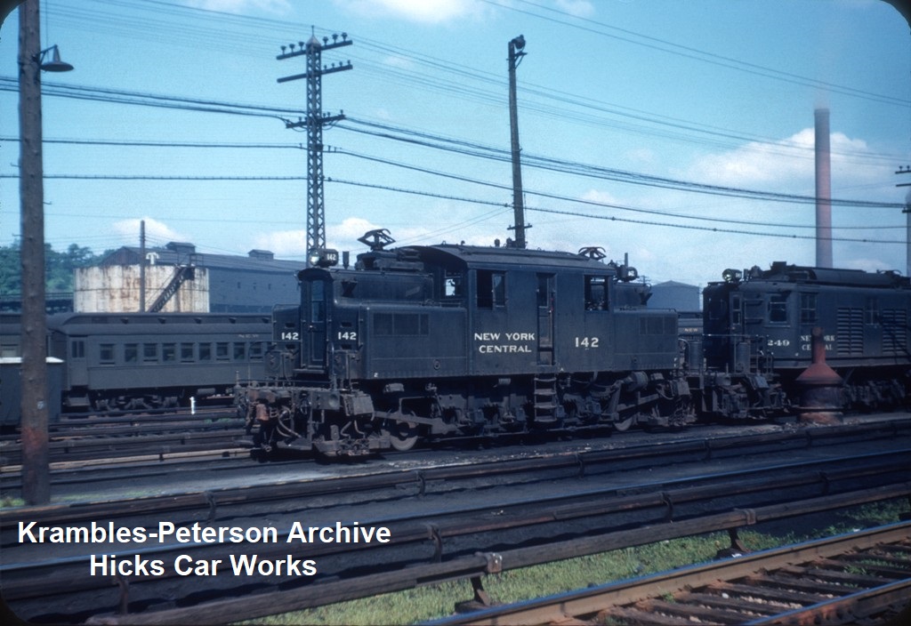
Number 142, an S-3 class locomotive with longer “porches” than the 1906-vintage S-2 locomotives, is at Harmon Yard with a T-motor behind it in this June 23, 1950, photo by Robert V. Mehlenbeck. Krambles-Peterson Archive.
At the same time, freight service, on the West Side Freight Line but also on the Hudson and Harlem lines, was rapidly being dieselized. The Q-motors were all retired and scrapped in 1955, replaced by Alco diesel switchers; the same year, almost the entire fleet of R-motors was disposed of. Most were scrapped, while some were sold to the Chicago South Shore & South Bend for rebuilding and continued service. The West Side Freight Line was de-electrified in 1959 and all duties were taken over by diesels.
Number 115 is southbound at 140th Street, approaching the Harlem River Bridge coming out of Mott Haven Yard, with sleeping cars in tow on June 7, 1958. New York Central System Historical Society Archive.
The S-motor fleet did not escape unscathed. During 1955 and 1956, more than a dozen S-motors were retired and scrapped, including all eight of the remaining S-3 motors, no longer needed for road trains following the arrival of the P-motors. Another half-dozen S-motors were retired between 1960 and 1962. In June 1963, one of the S-motors entered preservation when NYC President Alfred Perlman donated number 113 and a 4-8-2 Mohawk steam engine to the National Museum of Transportation near St. Louis. The following year, the very first S-motor – NYC 6000, the sole S-1, known since the 1930s as number 100 – was retired and ceremoniously presented to the nascent American Museum of Electricity. It was placed on display at the fairgrounds in Altamont, New York, west of Albany and only a few miles from the site of its 1904-1906 trials on the Schenectady test track.

The first S-motor, originally numbered 6000 and by this time numbered 100, is pictured at Harmon Yard near the end of its career. Krambles-Peterson Archive.
Number 102 has just pulled a train of cars out of Mott Haven Yard on its way south to GCT in this image snapped in June 1957 by Tom Desnoyers from the 144th Street bridge over the NYC. The observation car, “Babbling Brook,” still exists today and is in use as a private car. Tom H. Desnoyers Photo, Krambles-Peterson Archive.
With freight traffic being lost to trucks, the West Side Freight Line closing, and passenger traffic dropping off due to highway and airline competition, the need for the remaining electric locomotives in the NYC electric zone dried up and the S-motor fleet continued to contract. The venerable design’s one-time peers were already gone; the New Haven EP-1 boxcabs that had followed hot on the heels of the S-motors were all cut up by 1947, and the last of the similar EF-1 boxcabs went to scrap in 1957. The PRR DD-1s were conveyed to the Long Island Rail Road in the late 1920s and early 1930s, replaced by newer locomotives and then rendered entirely obsolete by the PRR’s conversion of its line through Manhattan to high-voltage AC, but by 1964 all were scrapped save for a single two-unit set the railroad marked for preservation.
But several of the S-motors soldiered on, even as newer locomotives went to scrap. In 1966, the remaining S-motors – by this time, all from the 1906 S-2 class – were renumbered into the 4700 series in anticipation of the coming merger with the PRR. That series had recently been vacated by the retirement of the Pennsylvania’s P-5a class, locomotives just over half the age of the S-motors. In 1968, the merger was finalized, and for the first time in their long career, the S-motors no longer wore “New York Central” on their flanks. They were now Penn Central locomotives.
On November 13, 1966, S-motor 110 pulled a railfan excursion that toured the electric zone. Here, the train is shown at North White Plains. The freshly painted, 60-year-old S-motor was one of the oldest locomotives in active service in the country. Gerald H. Landau Photo, Krambles-Peterson Archive.
PC 4715 is pictured at Harmon Yard on the last day of February 1973. New York Central System Historical Society Archive.
A total of 19 S-motors were still on the roster to receive 4700-series numbers, but five of those had been retired by 1968. As long-distance passenger service cratered, reducing the need for the core duties of the S-motors – switching passenger trains at GCT and deadheading passenger cars between the terminal and the Mott Haven yards – more locomotives were retired. By late 1969, only eight members of the class, now all more than six decades old, were still in service. In the early 1970s, as long-distance services were taken over by Amtrak, passenger train duties in and out of GCT were assumed by FL9s. These were EMD F-units specially modified to operate off either diesel power or 600V third rail. The remaining T-motors and P-motors were all retired save for a single T-motor kept as motive power for a wire train based in Sunnyside Yard in Queens. And yet the oldest locomotives of them all, the S-motors, remained in service.
When Conrail was created in 1976, the oldest locomotives on its roster – by decades – were five S-motors. Numbers 4715, 4723, 4725, 4731, and 4733 were still in service as switchers at GCT and at Harmon Yard. They were on borrowed time, though, and none was ever lettered for Conrail. Two additional locomotives were retired over the next few years until, in 1980, the increasingly decrepit state of the remaining S-motors impelled Conrail to find replacements. One of the smallest railroads folded into Conrail was the Niagara Junction Railway, an electrified switching line in Buffalo, New York. Conrail had taken down the NJR’s wires in 1977 and put into storage the line’s 25-year-old steeplecab switchers. In 1980, three of the switchers were pulled out of storage, refurbished, repainted in Metro-North Commuter Railroad colors and assigned to take over for the three remaining S-motors in GCT switching service.

On July 4th, 1976, on the bicentennial, S-motor 4733 pulled a three-car train of decrepit New Haven “washboard” MU cars on an Electric Railroaders Association excursion. The train is pictured at 125th Street, just south of the Harlem River. Gerald H. Landau Photo, Krambles-Peterson Archive.
By 1981, their 75th year, the S-motors were at the end of the line. A “Farewell to the S-Motors” excursion was scheduled for April of that year with 4715, the last of the series still in active use. Harmon Shop forces applied a fresh coat of black paint and Penn Central lettering in preparation for the curtain call. However, perhaps fittingly for a locomotive that had served so long, a mechanical failure sidelined the locomotive. The excursion’s riders had to be content to photograph S-motor 4715 in a prominent spot outside Harmon Shop. Although 4715 remained on the Conrail roster for another year, the 75 years of service for the S-motors was over.

Glistening in fresh paint, number 4715 is posed outside Harmon Shop for photographs during the “Farewell to the S-Motors” excursion on April 25, 1981. William J. Madden Photo, Krambles-Peterson Archive.
The Last S-Motor
The historic value of PC 4715 was obvious. It was one of the original production locomotives, delivered to the electric zone in October 1906 as NYC 3415. It had outlasted every other NYC electric locomotive, including the far newer T-motors, P-motors and R-motors. But although the last S-motor in service was clearly historic enough to preserve, where it might go wasn’t obvious. The steam railroad museums in the northeast weren’t interested, as they couldn’t operate it and it would be an obvious anachronism anywhere outside of the electric zone. The trolley museums in the region were designed for streetcars, not 115-ton mainline locomotives.
Nevertheless, the Branford Trolley Museum (today the Shore Line Trolley Museum) of East Haven, Connecticut, which owned a sizable collection of New York City streetcars and elevated cars, determined to ensure 4715 was saved. In September 1982, Branford authorized member Bruce Thain to purchase PC 4715 from Conrail. On December 21st of that year, Conrail moved the S-motor from Harmon Yard to GCT, and then on December 30th, it left GCT for the last time. It was moved to New Haven, Connecticut, and stored on the Connecticut Reserve track in the New Haven Yard.
This image, captured during the April 1981 excursion, shows 4715 being passed by its replacements: Conrail 4750 and 4753, ex-Niagara Junction steeplecabs soon to be renumbered 401 and 403, respectively. The steeplecabs would remain in service into the 1990s. William Hirsch Collection.
Branford’s plans for the locomotive were vague, with support for its acquisition divided between those who wanted it preserved at the museum and those who saw its acquisition simply as a stopgap to ensure it wasn’t scrapped. Among those who wanted to keep it at Branford, operation was apparently considered, but even before the locomotive arrived there were serious concerns voiced within the organization about the locomotive’s weight. Trucking it over the streets of East Haven could damage the roads, and once at the museum, there was the potential for damage to the track. In November 1982, the acquisition motion was amended to authorize static display only. The biggest obstacle, then as it is today, was the bridge: except for a narrow, uneven dirt road unsuitable for trucking railroad equipment, the only vehicle access to the Branford museum site is by rail over a wooden trestle. Proposals to reinforce the trestle with steel I-beams were vetoed by Branford volunteers. In January 1983, just weeks after the S-motor arrived in Connecticut, Thain was prohibited from making arrangements to move the locomotive to Branford without sufficient insurance against potential damages.
Over the next year, it became increasingly clear that there was no good way to get the S-motor to Branford’s site. Feelers were put out for a potential alternative home for the locomotive, and in March 1984, the Illinois Railway Museum made an offer. At the time, IRM was in the midst of an acquisition boom. Between 1980 and 1989, the museum acquired something like 125 pieces of equipment, more than in any decade before or since. In 1981, IRM had acquired a pair of giant electric locomotives: Chicago South Shore & South Bend (CSS&SB) 803, a 1948 2-D+D-2, and PRR 4927, a 2-C+C-2 class GG-1 built in 1942. The S-motor, something of a distant progenitor of both, would make a fine addition to the museum’s increasingly national collection.
Many Branford members, though, hoped the historic locomotive could be kept closer to its original territory. Through 1984 and 1985, there were various proposals floated to lease the S-motor back to the Metropolitan Transit Authority so it could be displayed at GCT. For better or worse, though, these proposals hit dead ends, and by the end of 1985 the concept was dead. In June 1986, it was formally proposed that Branford deaccession the S-motor, and that proposal passed in September. The locomotive was sold to IRM, a no-interest loan from IRM volunteer Bill Wulfert paying the purchase price. Volunteers Nick Kallas and Bill O’Brien traveled east to help prepare it for shipment. In early 1989, PC 4715 left Connecticut and traveled west.
The S-motor is pictured shortly after arriving at IRM, likely on the "steam leads." Ron Doerr Photo, IRM Collection.
Although a piece of traction equipment, responsibility for the S-motor was assumed by IRM’s Diesel Department – and volunteer Dave Dote had an idea of how the museum might get the locomotive operational. In early September 1991, a spare CSS&SB pantograph, salvaged from that company’s line car when the car was modernized, was fitted to the roof of the S-motor atop specially fabricated mounts that were designed for easy removal in the future. The locomotive’s air and electrical systems were tested, repairs were made as needed, and it was placed under wire. That month, the S-motor operated for the first time at IRM, making it the only S-motor ever to operate under power outside New York State.
The locomotive was not in pristine condition. The corners of the hoods had rusted through, and more problematically, one of its four motors was shorted. Nevertheless, on September 21, 1991, for the annual Member’s Day event, the S-motor pulled the caboose train between Boot Creek Bridge and Jefferson Street. Then as now, most of IRM’s overhead wire was not set up for pantograph operation, so the S-motor could only operate over a limited stretch of tracks.
Photos of locomotive 4715 in operation at IRM are exceedingly rare. This shot was most likely taken on September 21, 1991, when the S-motor saw a brief stint in passenger service at the museum. The photographer was the author, who was age nine at the time.
Unfortunately, the S-motor’s operational career at IRM was short-lived. The locomotive suffered from a number of air leaks and other minor problems, and volunteer time wasn’t available to address all the issues, so the S-motor was parked. It remained on outdoor display for many years and was also used as a portable air compressor, since shortly before it was retired by Conrail it had received a relatively modern 600V Gardner-Denver compressor. At one point there was a plan to acquire a CP-26A, the correct type for most of 4715’s career, but that fell through.
In the early 2000s, once additional indoor storage space became available with the construction of Barn 10, the S-motor was moved indoors. It spent some time in Barn 2, where it served as an air compressor for the diesel shop; then it was on display in Barn 9 for a time. When Barn 11 was constructed in 2009, the S-motor was moved into the building, taking it off display. It has remained in Barn 11 since that time, safely out of the weather but also out of sight. There are currently no plans to work on the locomotive.
Of the three S-motors still in existence, 4715 is almost certainly in the best condition. The first preserved, NYC 113, is still on display at the National Museum of Transportation, but is located outdoors and has suffered from weather exposure in much the same ways that 4715 did before it was moved inside. The first S-motor, NYC 100, fared far worse. The American Museum of Electricity, to which the locomotive was donated by the NYC, went defunct before ever constructing its museum. Number 100 then went to the Mohawk & Hudson Chapter of the National Railway Historical Society, which cosmetically restored it and even had it taken home to GCT for a movie shoot in the 1980s. But locomotive 100, coupled to the last surviving T-motor, was moved to an isolated power plant siding not long afterward, and remained there – relatively secure from vandalism, but increasingly derelict due to weather damage – for more than 30 years. By the early 2000s, the connection to the power plant siding had been severed, making the survival of the two NYC electrics questionable. Finally, in 2024, the Danbury Railway Museum dedicated a huge sum of money to have the S-motor and T-motor disassembled and trucked to the DRM site in Danbury. As of this writing, NYC 100 is in deteriorated condition and is still in two pieces – its frame and its body – but its future seems secure.
At some point in the future, with enough volunteer interest and money, IRM’s S-motor will be restored. It’s possible that the locomotive could operate again at IRM. Alternatively, the restoration may be a cosmetic one, perhaps including removal of the South Shore pantograph and restoration of the locomotive’s original, iconic profile. IRM is the only museum with examples of all three major mainline railroad electrifications to enter New York City. The museum’s PRR GG-1 and a 1956-vintage New Haven rectifier locomotive represent the two railroads that electrified their entrances to Manhattan shortly after the NYC did. The eldest of the trio, and arguably the forerunner of all the mainline electrification projects that came after it, is the iconic S-motor.

This is the S-motor’s current appearance, shown during a May 2016 switch move that brought the locomotive outside. Photo by the author.
Acknowledgements
Thanks to Art Peterson, William Hirsch, Ray Breyer, Robert McQueen, and the New York Central System Historical Society for providing photographs for use in this article; to Ray Breyer for digging up original NYC records; to Marcus Ruef and Jeff Hakner for providing background information on Branford’s part in the story; to Leah Johanson and the New York Public Library for providing materials from the William J. Wilgus Papers; and to Randall Hicks and Richard Schauer for technical assistance and proofreading.
Addendum A: Specifications for NYC 115
Builder: Alco/General Electric (builder # 29950/2115, order # S-216)
Delivered: October 1906
Length:
38’9” over coupler pulling faces
Width Overall: 10’0”
Height:
14’8” over retracted pantographs
15’6” maximum free height of pantographs
Wheel Arrangement: 2-D-2 (built as 1-D-1)
Tractive Effort Continuous Rating: 4,870 lbs.
Max. Tractive Effort at 25% Adhesion: 35,600 lbs.
Continuous Rated Speed: 60 to 70mph, depending on document
Max. Horsepower: 2,200 (per original specifications)
Continuous Horsepower: 1,050 (per 1917 specifications), 792 (per 1954 specifications)
Tonnage Rating: 550 (continuous), 750 (maximum)
Motors: 4 x GE 84A
Motor Voltage: 600V
Control Type: GE M (originally multiple unit, later single unit)
Master Controller: C79E (may have had a different type as built)
Running Speeds: 3 (series, series-parallel, parallel)
Control Contactors: DB-151B1, DB-267
Air Brake Schedule: #12EL double-end
Brake Valve: K-12
Air Compressor:
Sometime around the 1920s, this was replaced by a CP-26A
This compressor was replaced c.1980 with a Gardner-Denver compressor
As of 1926, some S-motors had CP-26A pumps and some had twin CP-19B pumps; by 1946, some had CP-26A pumps and some had CP-35A1 pumps. It’s conjecture, but likely, that 115 was never equipped either with twin CP-19B pumps or with a CP-35A1 pump.
Air Compressor Capacity: 100 cu. ft./min. (CP-26A)
Batteries:
Battery Capacity, Amp-Hours: 136
Battery Capacity, Kilowatt-Hours: 3.7
80psi oil-fired boiler with 1,550 lb. water tank (removed c.1920s)
Fuse cutters for third rail shoe fuse boxes
Side elevation of the S-motors as built. Locomotive Dictionary 1906.
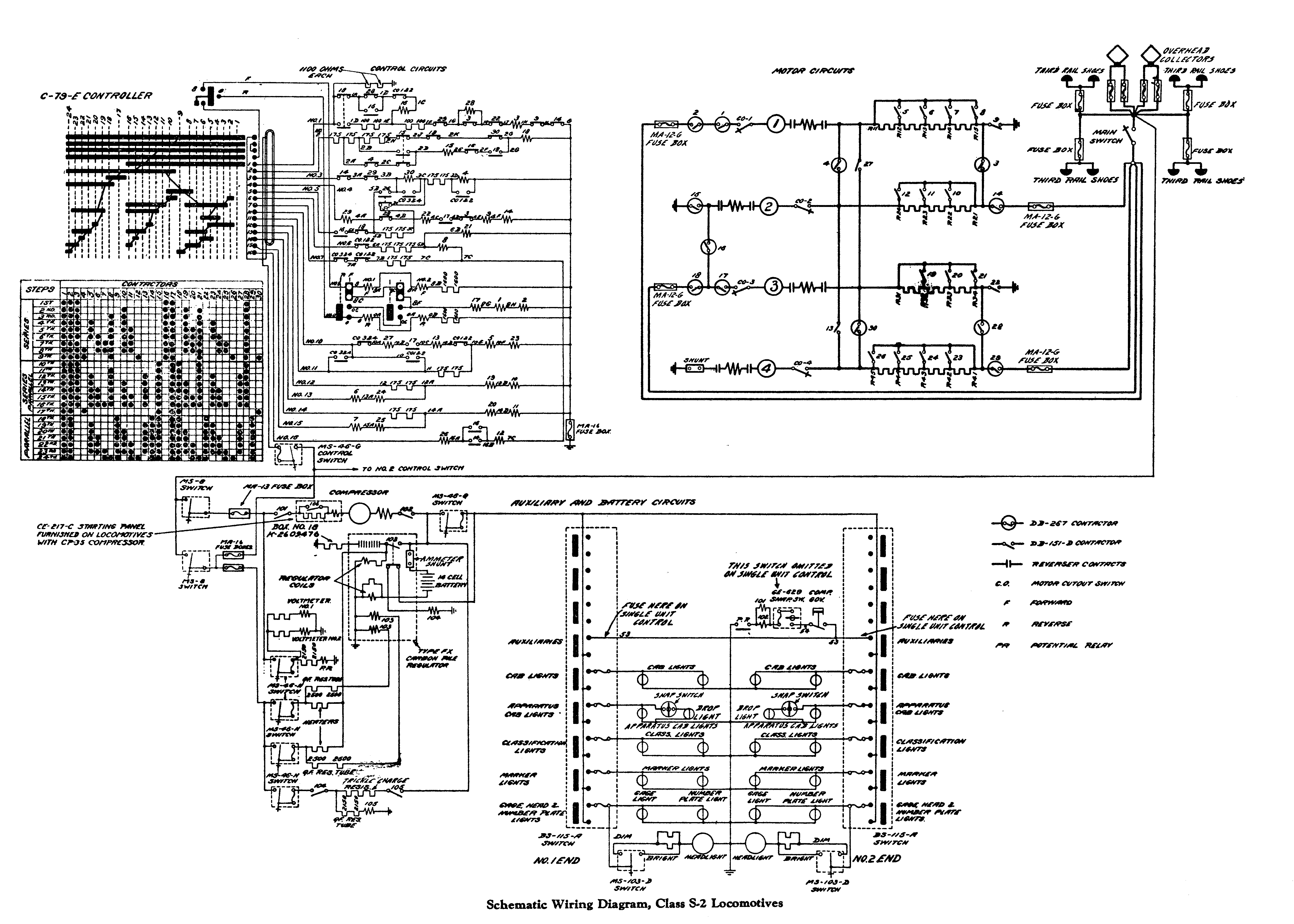
Wiring diagram. General Electric bulletin 1929.
Addendum B: In-Service Modifications to NYC 115
c.1908 – wheel arrangement changed from 1-D-1 to 2-D-2
– pilots replaced by footboards
– third rail shoe beams moved to ends of frame
– rearrangement of air tanks underneath cab
– brake rigging and brake cylinders relocated
c.1908-1910 – cab side windows changed from one- to two-pane
c.1910-1917 – pantograph and trolley fuse box locations swapped
c.1910-1917 – roof board and pantograph mount style changed
c.1910-1917 – double third-rail shoe fuse boxes combined into single fuse box
c.1910-1917 – air compressor radiating pipes added to cab rooftop
c.1910-1917 – grabs beside end doors extended onto roof
c.1910-1917 – spoked wheels on pony trucks replaced with solid wheels
c.1910-1922 – high, centered cab end window plated over
c.1917-1922 – markers and brackets added
c.1918-1925 – oil-fired steam boiler removed
c.1920s? – MU sockets removed
c.1920s – CP-19B air compressor replaced with a CP-26A
1929 – control system overhauled and line breaker contactors added
c.1929 – markers removed, brackets left in place
c.1980 – CP-26A air compressor replaced with a Gardner-Denver model
Renumbering History:
Built October 1906 as 3415
Renumbered September 1908 as 3215
Renumbered October 1917 as 1115
Renumbered August 1936 as 115
Renumbered 1966 to 4715
NYC became Penn Central in 1968, locomotive repainted as PC sometime thereafter
Penn Central became Conrail in 1976, locomotive not repainted as CR
Addendum C: S-Motor Roster
S-1 Class (Numbers – date built – builder numbers – date retired)
6000/3400/3200/1100/100 – 10/1904 – 29935, 2100 – 1964, to AMoE
S-2 Class (Numbers – date built – builder numbers – date retired)
3401/3201/1101/101 – 7/1906 – 29936, 2101 – 12/1960
3402/3202/1102/102/4702 – 7/1906 – 29937, 2102 – c1975
3403/3203/1103/103 – 9/1906 – 29938, 2103 – 11/1955
3404/3204/1104/104 – 9/1906 – 29939, 2104 – 2/1962
3405/3205/1105/105/4705 – 9/1906 – 29940, 2105 – c1969
3406/3206/1106/106 – 9/1906 – 29941, 2106 – 11/1955
3407/3207/1107/107/4707 – 9/1906 – 29942, 2107 – c1967
3408/3208/1108/108/4708 – 9/1906 – 29943, 2108 – c1969
3409/3209/1109/109/4709 – 9/1906 – 29944, 2109 – 1966
3410/3210/1110/110/4710 – 9/1906 – 29945, 2110 – c1976
3411/3211/1111/111 – 9/1906 – 29946, 2111 – 11/1955
3412/3212/1112/112/4712 – 9/1906 – 29947, 2112 – c1967
3413/3213/1113/113 – 10/1906 – 29948, 2113 – 9/1962, to NMoT 1963
3414/3214/1114/114 – 10/1906 – 29949, 2114 – 3/1956
3415/3215/1115/115/4715 – 10/1906 – 29950, 2115 – 1981, to BERA 1982
3416/3216/1116/116 – 10/1906 – 29951, 2116 – 11/1963
3417/3217/1117/117/4717 – 9/1906 – 29952, 2117 – c1967
3418/3218/1118/118/4718 – 9/1906 – 29953, 2118 – c1969
3419/3219/1119/119 – 10/1906 – 29954, 2119 – 2/1962
3420/3220/1120/120 – 9/1906 – 29955, 2120 – 2/1961
3421/3221/1121/121/4721 – 10/1906 – 29956, 2121 – c1967
3422/3222/1122/122 – 10/1906 – 29957, 2122 – 3/1961
3423/3223/1123/123/4723 – 10/1906 – 29958, 2123 – c1980
3424/3224/1124/124/4724 – 10/1906 – 29959, 2124 – c1969
3425/3225/1125/125/4725 – 11/1906 – 29960, 2125 – c1981
3426/3226/1126/126 – 10/1906 – 29961, 2126 – c1965
3427/3227/1127/127/4727 – 10/1906 – 29962, 2127 – c1969
3428/3228/1128/128 – 11/1906 – 29963, 2128 – 5/1963
3429/3229/1129/129 – 11/1906 – 29964, 2129 – 4/1962
3430/3230/1130/130/4730 – 11/1906 – 39735, 2455 – c1969
3431/3231/1131/131/4731 – 11/1906 – 39736, 2456 – c1981
3432/3232/1132/132/4732 – 11/1906 – 39737, 2457 – c1969
3433/3233/1133/133/4733 – 11/1906 – 39738, 2458 – c1978
3434/3234/1134/134 – 11/1906 – 39739, 2459 – 3/1956
S-3 Class (Numbers – date built – builder numbers – date retired)
3435/3235/1135/135 – 11/1908 – 45290, 2874 – 9/1955
3436/3236/1136/136 – 12/1908 – 45291, 2875 – 9/1955
3437/3237/1137/137 – 1/1909 – 45292, 2876 – 9/1955
3438/3238/1138/138 – 1/1909 – 45293, 2877 – 9/1955
3439/3239/1139/139 – 1/1909 – 45294, 2878 – 11/1946
3440/3240/1140/140 – 1/1909 – 45295, 2879 – 8/1955
3441/3241/1141/141 – 2/1909 – 45296, 2880 – 8/1955
3442/3242/1142/142 – 2/1909 – 45297, 2881 – 9/1955
3443/3243/1143/143 – 2/1909 – 45298, 2882 – 9/1955
3444/3244/1144/144 – 2/1909 – 45299, 2883 – 5/1955
3445/3245/1145/145 – 2/1909 – 45300, 2884 – 9/1955
3446/3246/1146/146 – 2/1909 – 45301, 2885 – 11/1946
Addendum D: Proposals Received in 1903
The William J. Wilgus Collection at the New York Public Library includes a document summarizing all the proposals sent to the NYC&HR in 1903 for the planned order of 30 to 50 electric locomotives.
- Brown, Boveri & Co. (Ltd.) – $24,340 for electric equipment only (the bidder was unable to arrange with any American builder to furnish complete locomotives), 4 x 300HP gearless DC motors intended for a steeplecab, eight-wheel, rigid-truck locomotive
- Siemens-Schuckert Werke - $27,405 for a steeplecab, eight-wheel, rigid-truck, articulated-frame [presumably a double-truck locomotive similar to ComEd 4 at IRM] locomotive with 4 x 400HP geared DC motors; the builder would also quote on a single-phase AC locomotive if desired
- Westinghouse Electric & Mfg. Co. - $27,900 for a box-cab, eight-wheel, rigid-truck locomotive with 4 x 375HP geared DC motors; the builder would also quote on gearless motors or on a single-phase AC locomotive if desired
- American Electric Securities Co. - $34,810 for a steeplecab, 120,000 lb., 33’10” long rigid-truck locomotive with 4 x three-phase AC motors of indeterminate horsepower [it’s not clear who would have actually built this, as AES was not a locomotive manufacturer]
- General Electric Co. – submitted proposals for 12 different locomotive designs:
- $33,800 for a rigid-wheelbase, 170,000 lb., 35’0” long locomotive with 4 x 550HP gearless DC motors and pony trucks [this is effectively what ended up being built]
- $32,800 for the same type as design (1) but without pony trucks, weight 150,000 lbs., length 28’0”; a note was included that GE recommended one of these two designs
- $44,000 for a 12-wheel, articulated-frame, 220,000 lb., 38’6” long locomotive with 6 x 350HP gearless DC motors [this sounds similar to a 1930-era R-motor]
- $30,800 for a rigid-wheelbase, 170,000 lb., 36’2” long locomotive with 4 x 400HP geared DC motors and pony trucks
- $29,500 for a rigid-wheelbase, 150,000 lb., 32’0” long locomotive with 4 x 400HP geared DC motors; a note was included that this design was closest to that specified by the railroad
- $36,600 for a rigid-wheelbase, 184,000 lb., 38’4” long locomotive with 4 x 500HP geared DC motors and pony trucks, described as similar to design (4) but with larger motors
- $35,500 for the same type as design (6) but without pony trucks, weight 166,000 lbs., length 34’3”
- $39,000 for a similar design to design (3) but with 6 x 325HP geared motors, weight 212,000 lbs., length 43’0”
- $36,000 for the same type as design (7) but with four-wheel bogie trucks, 4 x 500HP geared motors, weight 171,000 lbs., length 42’0”
- $38,000 for a design with the same equipment as design (8) but with bogie trucks and equalizing gear, weight 202,000 lbs., length 49’6”
- $40,000 for a rigid-frame, 224,000 lb., 51’8” long locomotive with 8 x 250HP geared DC motors and bogie trucks with equalizing gear to rigid trucks [it’s not clear from the description whether this design is similar to the 1910-era T-motor]
- $49,000 for a locomotive with an articulated frame like designs (3) and (8) with 6 x 300HP geared DC motors, weight 220,000 lbs., length 47’3”
General Electric submitted that if AC motors were used, they would need to be geared and at least six per locomotive would be needed, making an articulated-frame or bogie design necessary. GE also submitted five different forms of cab: rounded ends with or without platforms, truncated ends with or without platforms, and wedged (steeplecab) ends with platforms. GE said that the first four types could be fitted with vestibules, i.e. covered passageways, though a later drawing reproduced in this article showed a locomotive with “wedged” ends and “vestibules” nonetheless.