From the company archives, here are some multiple unit control wiring diagrams you might find useful. Further contributions would be welcome.
General Electric
C-6
C-6

This is the basic multiple-unit control system with manual acceleration and open transition. There are 13 contactors, with no line breaker. The C-6 controller was widely used throughout the industry during the early days of MU control.

For the first order of cars on the AE&C, with four GE-66 machines the solution was a double set of contactors and reversers.

The C-6 control system was modified by the AE&C: by adding some interlocks, one control wire was no longer needed to operate the control and was used instead to connect the buzzers throughout the train. This also made it compatible with the C-21, shown below. (This is several scans pasted together from a copy of several smaller copies taped together.... so I'm looking for a better version!)
 The above diagrams don't include a sequence chart, so here's one I made up. I should note that the contactors are arranged in a slightly different order on some of our CA&E cars.


The C-18 was an early form of automatic acceleration. The controller drum is connected to the handle via a spring. When the controller handle is advanced, the drum rotates unless the lock magnet is engaged. The lock magnets in each controller are connected to control line 10 and are energized whenever the motor current in any car is sufficient to raise the current relay, shown in this diagram inside the electrical cabinet (upper middle of the page). This system was used on the Interborough "Hi-V" cars, and is still functional on one such car at Seashore.
The above diagrams don't include a sequence chart, so here's one I made up. I should note that the contactors are arranged in a slightly different order on some of our CA&E cars.Chicago and Milwaukee Electric

Here is another version of C-6, as used by the C&ME on their wooden interurban cars.

There was no law that the contactors had to be in the same order, so like the CA&E, more than one arrangement was used.
C-6 with DB-409 Reverser and Field Tap

This appears to have been another one-off design for the CA&E. About 1920 three cars (319-321) were re-equipped with GE 254 machines, and this required a four-motor control system with automatic field tap. This system is compatible with the earlier C-6 and C-21 equipments. All three cars have been preserved.

A close-up of the interlock wiring.

And a simplified sketch of the above, control circuits only. It's a mirror image for debugging purposes because these connections are only accessible from the back of the box.
C-18

The C-18 was an early form of automatic acceleration. The controller drum is connected to the handle via a spring. When the controller handle is advanced, the drum rotates unless the lock magnet is engaged. The lock magnets in each controller are connected to control line 10 and are energized whenever the motor current in any car is sufficient to raise the current relay, shown in this diagram inside the electrical cabinet (upper middle of the page). This system was used on the Interborough "Hi-V" cars, and is still functional on one such car at Seashore.
C-21
 From March 1906, this is a slight modification of the C-6 system using the same basic principle as the C-18. We believe the C-21 was unique to the CA&E. Each controller had a mechanical automatic acceleration feature, controlled by the DB-115 relay shown next to the cutout switch. Each controller has a lock magnet which prevents it from being moved. This feature was soon removed by the railroad, but otherwise this is the system still installed on cars 303 and 308.
 Note: Control line 7 was used to connect the lock magnets on all controllers. It is energized through contactor 3, which is on in every point, and the DB-115 relay, which is energized on any car in which the motor current exceeds a set value. Thus the lock magnets on every controller are turned off only when all cars have low motor current. Of course the lock magnets are off when power is shut off.
Automatic acceleration did not last long on the CA&E, and line 7 was then used for the buzzer.
C-74

This is a more advanced manual acceleration system with closed transition. There are 12 contactors, with no line switch but an overload relay. The C-74 was widely used, and there are many preserved cars with this control.

This is the wiring diagram for the IT Class B at IRM, 1565. There are 39 contactors but no reverser, as that work is done using contactors. There are also series, series-parallel, and parallel points. In the 1940s, a 40th contactor was added, which appears on later sequence charts - it's "in" on all points. As of this writing, we aren't certain of its purpose.

This is the wiring diagram for the two GE steeplecabs on the CA&E, 2001 and 2002, with manual acceleration and closed transition. This control was also used on a YVT steeplecab preserved at Yakima.

This is a more advanced manual acceleration system with closed transition. There are 12 contactors, with no line switch but an overload relay. The C-74 was widely used, and there are many preserved cars with this control.
C-83A

C-90

C-96

This is another version with manual acceleration and closed transition. Since this is a simplified diagram, several details are left out.
C-101

This is the wiring diagram for Charles City Western #300, a dual-voltage (600/1200) locomotive. It is not the usual application of the C-101 controller, and may be unique to this particular unit. There are 14 contactors with closed transition. There is no line switch, but a DB-102 circuit breaker. Note that the two pairs of motors are wired in series for operation on 1200V.
C-165

This is a later manual acceleration system with closed transition, and includes overload relay, potential relay, and automatic field tap. This was used on the CA&E Pullman and Cincinnati cars. There's an amusing note on what to do if the car is going the wrong direction.
"Proto-165"
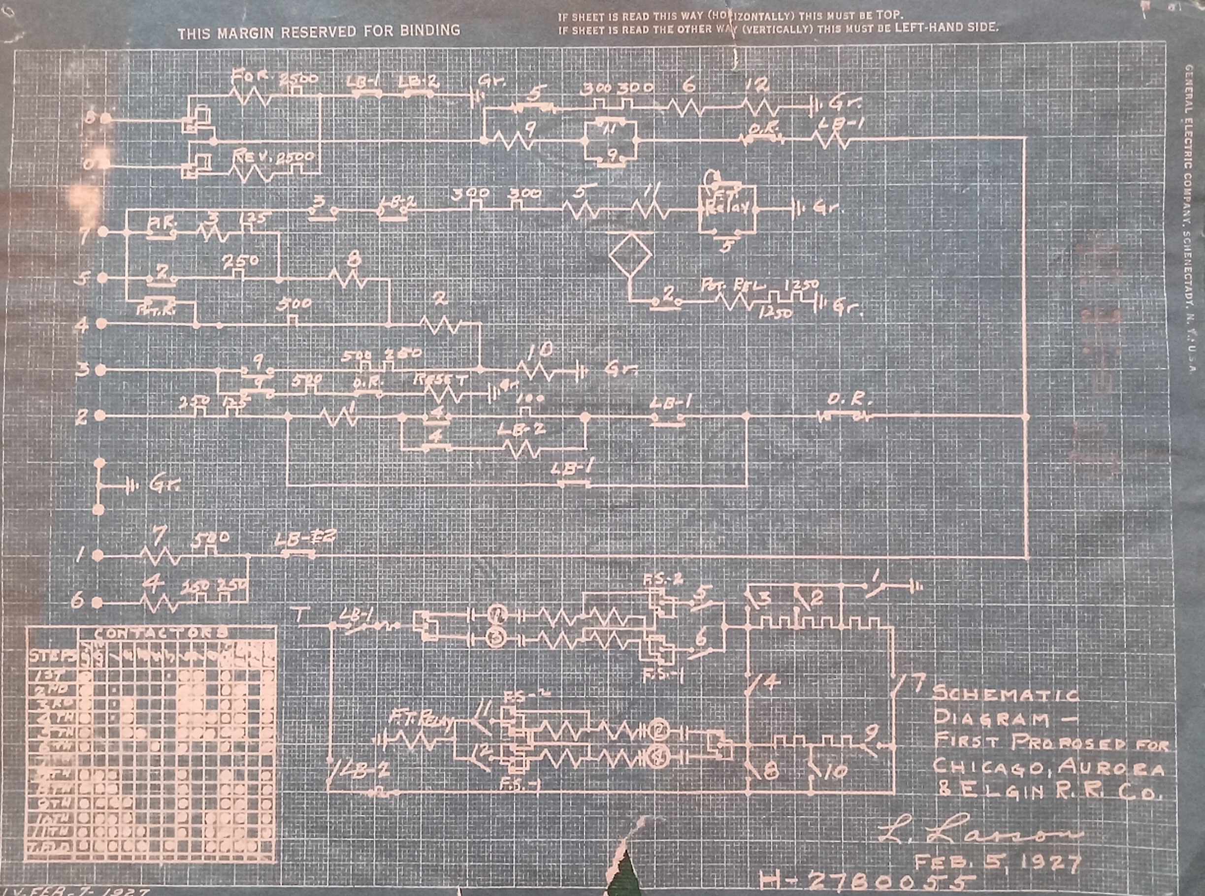
Here's something interesting: the original basic design for the C-165 system. Several changes were made in the production version.
17KC54A1


This is the control system for the CA&E St. Louis cars. It's a large print, 56" wide, so I had to scan it in two parts. This system had to be compatible with the C-165 system above, but it is designed for use with 300V machines so among other things the cutout system is different.
Automatic Acceleration
 Here's a simplified diagram from Norris which will help explain how the GE type M automatic acceleration control worked. The motor circuits are not shown, but we have three contactors, each of which cuts out some resistance and thus increases the motor current. Each contactor has four interlocks, two NC and two NO.
There are two control circuits: "Circuit #2" at the top is the holding circuit, and "Circuit #1" is the lifting circuit. The lifting circuit is governed by the throttle relay at the right side of the diagram. The holding circuit is always energized. (I'm not sure why the cutout relay is shown; we have to imagine it's always on.) When power is first applied, current flows through the throttle relay to the lifting circuit, and you can see that the interlock on contactor #1 energizes the coil and lifts the contactor. The upper interlocks then energize the coil through the holding circuit. Meanwhile, there's enough motor current to raise the throttle relay and disable the lifting circuit. After a few seconds, the car has gained enough speed to reduce the motor current and allow the throttle relay to drop. The interlocks then direct the current in the lifting circuit to raise contactor #2. Contactor #2 is then also held up by the holding circuit, and due to the increase in motor current the throttle relay opens again, turning off the lifting circuit. And this process continues in an obvious fashion. Once you understand this, you're ready for....
C-36
Here's a simplified diagram from Norris which will help explain how the GE type M automatic acceleration control worked. The motor circuits are not shown, but we have three contactors, each of which cuts out some resistance and thus increases the motor current. Each contactor has four interlocks, two NC and two NO.There are two control circuits: "Circuit #2" at the top is the holding circuit, and "Circuit #1" is the lifting circuit. The lifting circuit is governed by the throttle relay at the right side of the diagram. The holding circuit is always energized. (I'm not sure why the cutout relay is shown; we have to imagine it's always on.) When power is first applied, current flows through the throttle relay to the lifting circuit, and you can see that the interlock on contactor #1 energizes the coil and lifts the contactor. The upper interlocks then energize the coil through the holding circuit. Meanwhile, there's enough motor current to raise the throttle relay and disable the lifting circuit. After a few seconds, the car has gained enough speed to reduce the motor current and allow the throttle relay to drop. The interlocks then direct the current in the lifting circuit to raise contactor #2. Contactor #2 is then also held up by the holding circuit, and due to the increase in motor current the throttle relay opens again, turning off the lifting circuit. And this process continues in an obvious fashion. Once you understand this, you're ready for....
C-36
 This is the basic GE type M automatic acceleration system in all its glory, with 43 interlocks. There are 12 contactors, with closed transition and no line switch.
LSE Version of C-36

Here is a C-36 control system as modified for use on Lake Shore Electric interurban cars with four motors. Changes to the control system were often made when new designs were being put into service. Thanks to Dennis Lamont for sending this diagram.
This type M automatic acceleration was replaced about 1915 by PC (pneumatic cam) control, based on a rotating shaft with cams to drive pneumatic contactors. PC control is simpler and presumably more reliable.
NYC S Motor
C-79E
 This is just the motor circuit diagram for the NYC S motor, with its 47 contactors (each represented by its number). I shudder to think what the control circuits would look like. These locomotives had automatic acceleration similar to the C-21 above: if motor current is too high, a lock magnet prevents the motorman from advancing the controller. The controller has 24 points, so sequencing this thing could take a while!
South Shore 803
C-195D1

This is GE Type P control (if M = Magnetic, P = Pneumatic) as used on the South Shore 800-series locomotives. The print is very long and these images are reproduced in such a way that they should be read left-to-right. The sequence chart includes 37 controller points, an additional 24 steps for field shunting and transition, and 71 contactors. Thanks to Richard Schauer for scanning this print.


Westinghouse
HL

This is a basic diagram for a Westinghouse MU control; this is an HL system.

And here is another HL circuit diagram, this one for Indiana Railroad 205. Thanks to Dave Beuchler, who knitted this together from images of the original in IRM's files.
Here is an HLF system as used on the Cleveland Railways 1200-series center door cars. Thanks to Steve Heister, who found this in the Brookins collection.
This is an HLF system for an application described only as "DC Loco - 4 motors - 600V". It has the same controllers, so it might even be identical to the one above -- with these screwy Westinghouse diagrams, who can tell?


This schematic might help -- much easier to understand!
 This is a Westinghouse system with automatic acceleration and battery power, hence AB. Like the GE system, there is a limit switch and a series of interlocks to provide the automatic acceleration.
Whereas the various GE systems are identified by numbers, Westinghouse controls are identified by letters specifying the features, as follows:
A - Automatic acceleration
B - Battery power
F - Field tap
H - Hand (non-automatic) acceleration
L - Line power
M - Compatible with GE M controls
X - Experimental models
A - Automatic acceleration
B - Battery power
F - Field tap
H - Hand (non-automatic) acceleration
L - Line power
M - Compatible with GE M controls
X - Experimental models
HL
This is a basic diagram for a Westinghouse MU control; this is an HL system.
HLF

And here is the HLF system for the B-W Class D locomotive. Of course, this could also be used on home-built locomotives, such as the Crandic 72-73 (later CA&E 4005-4006). Controllers are type 337-D-2.

This is an HLF system for an application described only as "DC Loco - 4 motors - 600V". It has the same controllers, so it might even be identical to the one above -- with these screwy Westinghouse diagrams, who can tell?


This schematic might help -- much easier to understand!
AB
This is a Westinghouse system with automatic acceleration and battery power, hence AB. Like the GE system, there is a limit switch and a series of interlocks to provide the automatic acceleration.HB

Here is the HB Westinghouse system used on the North Shore Electroliners. This is for the A and A1 cars; the other half of the train has another set of equipment. Electrically, the Electroliner is a pair of four-motor cars with an idler truck in the center..
Control Jumpers
These are taken from wiring diagrams above, but my versions are easier to read, I hope.