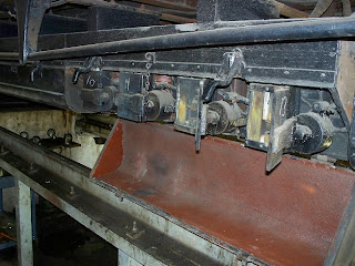
Annual inspection work on the 309 provided a good opportunity to document and explain the operation of the contactors on this car. First, some history: the first successful multiple-unit operation was in Chicago, in 1898, using a system designed by Frank Sprague for the South Side Rapid Transit. Three years later, General Electric developed the first widely-used form of electomagnetic contactor control, known as Type M. Type M was a system which used a master controller to energize different high-voltage, low-current circuits which in turn activated large contactors under the car. These contactors were activated in combinations that routed motor current through different sets of resistance grids, thereby controlling motor speed and, hence, acceleration.
The first widely-used Type M system consisted of DB-15 contactors, DB-20 reversers and C-6 controllers designed in 1901 for the electrification of the large Manhattan Elevated system in New York. When the Aurora Elgin & Chicago (predecessor to the CA&E) was built a year later, the most modern MU system available for heavy electric equipment was the system developed for Manhattan. The AE&C wanted four GE 66 motors per car, though, and since the DB-15 contactors were only designed for two of these motors, the early AE&C cars were basically two two-motor cars back-to-back. Each car had two complete sets of contactors, reversers and grids. Car 309, though built five years later after the development of more modern Type M systems, was equipped with the earlier DB-15 contactors - probably because it was fitted with electric equipment at Wheaton Shops, which likely used whatever spare parts they had lying around.

I also recorded a brief video demonstrating the components and operation of the DB-15 contactor, including interlocks. Interlocks are safeguards incorporated into the design as separate circuits that prevent various bad things from happening accidentally, like activating the reverser while motoring or energizing series and parallel circuits simultaneously.
News and views of progress at the Illinois Railway Museum
Monday, May 25, 2009
Contactor Operation
Posted by
Frank Hicks
at
12:01 PM
![]()
Labels: Mechanicals
Subscribe to:
Post Comments (Atom)

No comments:
Post a Comment