Monday, October 19, 2020

Van Dorn Coupler Company - Link and Pin Couplers

The invention that brought William T. Van Dorn fame and fortune, and the piece of equipment most closely associated with the name Van Dorn, was the automatic link-and-pin coupler. I'm not positive exactly when Van Dorn patented his first automatic link-and-pin design but it appears to have been the 1880s, a time when couplers were quickly becoming one of the aspects of railroading in most obvious need of improvement. Standard link-and-pin couplers were incredibly dangerous; the tenure of conductors and brakemen could generally be measured in fingers lost. Deaths from having to go between cars to make and break trains were common.

Van Dorn's invention, the automatic link-and-pin coupler, built on existing technology but sought to make it unnecessary to stand in between cars being coupled. Van Dorn couplers are described here, but briefly, the coupler head was designed so that a pin could be placed in one of two vertical holes and so that a spring on one side of the coupler head could apply sideways pressure to the link. The link itself was symmetrical, with a hole in the middle and a hook at each end. To couple two cars, a link was pinned into one coupler using the hole in the link, while in the other coupler (with no link), its pin was placed in an offset hole in the coupler head. When the cars were pushed together - without the need for anyone on the ground or near the coupler at all - the link hooked onto the pin in the other coupler, the spring built into the coupler head keeping it from unhooking.

This drawing showing how the coupler works is from patent 711549


This system was inferior to knuckle, or MCB, couplers for heavy freight service and by the mid-1890s MCB couplers (which Van Dorn also manufactured) were standard on steam railroads. But the Van Dorn link-and-pin coupler was lighter and easier to maintain than MCB couplers so it found favor with street railways, interurbans, and rapid transit lines. Van Dorn couplers were in use on the CA&E until 1957 and on the CTA, in work service, into the 1970s. Van Dorn itself offered a range of couplers, varying mainly in their size. There were also a variety of offerings for draft gear.

The following illustrations are among the original Van Dorn Coupler Company materials donated to the Illinois Railway Museum by Larry Larson. The images are the property of the Illinois Railway Museum and may not be reprinted without permission.

#4A Coupler

Here we have a #4A coupler with a #16 link and a #16 pin. There are quite a few illustrations in the donated Van Dorn materials of early link-and-pin style Van Dorn couplers, but unfortunately the biggest difference between them is often their size, and in the absence of any background their size is difficult to gauge.

Here's another #4A coupler, or coupler head, but this time it's paired with #104 draft gear.

This #4A coupler is fitted to #36 draft gear with a #36D anchor casting and a #1145 anchor. The two preceding images both show up in the coupler catalog.

The Northwestern Elevated Railroad apparently used #4A couplers, as the ex-Northwestern 'L' cars at IRM including 1754, 1797, and 1808 all have this type. Photo by Bill Wulfert.

#5 Coupler

It appears that the #5 coupler was one of the smaller couplers made by Van Dorn. It was evidently recommended for streetcar use. That curved top to the coupler's buffer face is interesting. This illustration notes that the coupler has a #5 link and a #5 coupling pin.

Unfortunately this illustration took some damage, but it shows a #5 coupler head at the end of a reasonably long bar attached to a #14 ball joint (this image shows up in the coupler catalog).

This is described as a #5 coupler head with a #5 link, #5 coupling pin, and a #14 ball joint. It even points out that a 1"x3" short bar is used for the shaft.

This is described as a #5-1/2 coupler. Van Dorn didn't limit itself to whole numbers in its coupler designations. We found a pair of drawings, one for a #5 coupler and one for a #5-1/2 coupler, and the only differences seem to be the size of the intended shaft and the height (not width) of the strike face on the coupler, which was higher on the #5-1/2 than on the #5. I suppose that the differences were slight enough that they didn't feel compelled to use an entirely new number.

#11 Coupler

Here we have a #11 coupler head with a #11 link and a #5 coupling pin.

This illustration is described as "#11 or 11-1/2" so perhaps the differences between those two types were very minimal. Or perhaps the person writing those notes on the photos a century ago just wasn't sure. Regardless, this one too has a #11 link and a #5 coupling pin according to the note.

This is an actual photograph, not an illustration, and it is described as a #11-1/2 coupler.

And this, apparently, is the illustrated version of the above photo. It's described as "#11 or 11-1/2" but since the photograph is described as a #11-1/2, and it looks very much like this was based off of the above photograph, I suppose it's a #11-1/2. The illustration also says that it has a #5 coupling pin (note that the pin may actually be different than what's in the above photo) and a #100 stop casting.

#16 Coupler

This is a #16 coupler head and is noted as having a #16 link and a #16 coupling pin. This type of coupler is a bit unique because I stumbled upon a description of when it was designed and for what purpose. In, 1901 Street Railway Review (link here) published a brief article about Van Dorn designing the #16 (for motor cars) and #15 (for trailers) couplers specifically for use on the new Manhattan Railway elevated system electrification. There's also an illustration showing a drawbar of extravagant length connected all the way back to the car's body bolster. The #16 is also the type of Van Dorn coupler used by the CA&E on its wood cars, which makes sense given that when the CA&E first opened in 1902 its cars also used motors and control equipment that had been designed for the Manhattan Railway electrification project the year before.

#18 Coupler

Here's a #18 coupler head with a #16 link and #16 coupling pin. This style of coupler head was designed with a channel down the back of the coupler head suitable for mounting to a section of rail.

The #18 coupler is the type used on IRM's two Metropolitan-West Side Elevated cars, 2872 and 2888. This photo was taken by Bill Wulfert of the trailer end of the 2888 showing the car's coupler and the draft gear, which uses 80# rail. Photo by Bill Wulfert.

#19 Coupler

The #19 coupler shown here is fitted with a #19 link and a #1121 coupling pin. This coupler appears in a 1907 Street Railway Journal article (link here) and is described as being the "latest type, embodying several new features." It can therefore be supposed that this type was developed around that time.

#20 Coupler

This isn't actually a #20 coupler; there aren't any illustrations of a #20 among the Van Dorn records we acquired. Rather, this is a #20-1/2 coupler head with a #19 link and a #17 coupling pin. It's also noted as having a "special carrier."

This setup looks bizarre, but it resembles the proposed mounting of the #16 couplers linked above and it was actually in the Van Dorn catalog. It's described as a #20-1/2 coupler head "with rail draft gear" (I guess that about covers it!). Sure enough, I came across a description of the original series of Hudson & Manhattan subway cars and they were described as having drawbars of "85-lb. bent rails with Van Dorn couplers."

#21 Coupler

This is a #21 coupler with #200 draft gear. The coupler head fits onto a section of rail used as the shank, and the following illustration shows a channel in the back of the coupler head for this purpose. This image shows up in the coupler catalog)\.

This is described as a "#21 or 21-1/2" coupler head with a #11 link and a #5 coupling pin.

This is another "#21 or 21-1/2" coupler head. It's got a #11 link, a #5 coupling pin, a #200 swivel casting, and it uses 60-lb rail for the coupler shank.

#27 Coupler

Here's a #27 coupler head with a #11 link and a #5 coupling pin. I believe the #27 is the only Van Dorn coupler shown in the files with that "wishbone" looking design cast into the top.

Here's the same coupler from a different angle. Again, it's a #27 coupler head with a #11 link and a #5 coupling pin.

This #27 coupler is fitted to #332 draft gear. This image shows up in the coupler catalog.

#29 Coupler

This is a #29 coupler head with a #11 link and a #5 coupling pin. This coupler head is apparently designed to fit onto a section of rail.

#37 Coupler

The highest-numbered link-and-pin coupler included in the materials that were donated is the #37, shown here with a #19 link and a #19 pin.

Other Hardware

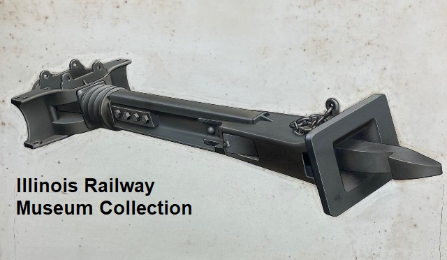
It's obvious that Van Dorn didn't just make couplers; they also made draft gear and other associated components. Here we see a #11 ball joint on the left with a #515 anchor on the right.

Sunday, October 18, 2020

Saturday News Brief

As usual, this is a random sample of what was going on in Barn 4.  Several other working members got cheated out of their rightful share of publicity by not being in the right place at the right time.  Luckily for me, most of them are not the litigious sort.

Of course, I tend to focus on what I'm doing, because it's right there in front of me.  Installing new wood at the #2 end of the 453, for instance.  (The C clamp is just acting as a weight for the glue.)


Then more of the tack molding got our magic epoxy rejuvenation treatment.


New wood fitted and installed for patching up this gaping hole in the roof.


Followed by installation of some of the thin strips we had on hand from an earlier project.  This is mostly just the first layer.


Zach was working on end windows for the 757...


 and since he had the paint out, he was nice enough to finish putting primer on Frank's signal box.


It's still a matter of conjecture and contention just what this was for.


It's over in the truck shop that the heavy lifting takes place.  Greg is working on one of the trucks for the CLRV, which need to be regauged.   Ugh.


Ed is moving parts for the Cleveland PCC truck.


Finally, Bill is putting up pieces of newspaper so he'll have something to read while he spray-paints the grid boxes on the 1754.  There are still some parts of the underbody equipment on this car that need finishing.

And as usual, it was more fun to be there in person.

Happy birthday!


Happy birthday to our head blogger, famed restorationist Randy Hicks! This recent photo was taken before he turned 39.

Friday, October 16, 2020

Interurban to Villa Park

On my recent trip out west, I also had a chance to examine the other preserved car from the Denver and Intermountain, this one a complete wooden interurban car which has been restored and kept in pristine condition.  It now belongs to the city of Lakewood, another Denver suburb, and is stored under cover on the grounds of a large federal facility.  Of course, I had to laugh when they opened the door and I saw how it was signed:


The facility, now used by federal office workers, was a Remington Arms plant during WWII and for several years after.  The plant was switched by a Diesel housed in this shed, now used by the 25.


And outside is the generator on a cart which powers the 25, since they can't install overhead wire:


K-35G controllers.  


All of the car cards looked strangely familiar.


Woeber Carriage was indeed originally a carriage builder, and seems to have sold railway cars only to Colorado roads.  Most of the preserved cars from Colorado were built by Woeber.  As Wally pointed out, for this order of three interurban cars, they seem to have copied Niles designs.  


There are no electrical cabinets.  Switches and fuses are attached to any available surface.  This is probably not unusual; it appears that the CA&E shorties were built without cabinets and were probably arranged this way.  The drawbacks are obvious.


In addition to the original equipment, controls have been added for the generator cart and the marker lights, which have been converted from kerosene to electric.


They have a nice collection of tools and parts for minor repairs:


The original doors:


And part of the original siding:


Mathematically, it's surprising that the two cars preserved from this railroad are inverses of each other.  What is the probability of that?  (Be sure to show your work!)


The upper sash windows have this nicely etched pattern:


The car was probably built with straight air, but later converted to automatic, with the triple valve mounted on the brake cylinder, and an automatic slack adjuster.  I didn't get the model number.


When the D&IM ended passenger service in 1950, this car was acquired by the Rocky club, and stored on a siding in an on-line lumber yard.  For the next three years, freight service continued with electric power, and the club could occasionally bring the car out and run fan trips on the main line.  After that, it was stored in various places until the current arrangement was available.  The largest part of the restoration was done by one man, Darrell Arndt, who put in at least 5,000 hours, as well as helping fund the restoration by the club and its foundation.  The car now belongs to the City of Lakewood, in cooperation with the club, and once a year they run the car back and forth on about a quarter mile of track for the citizens.  Otherwise, normally it's not accessible to the public.


The car faces an uncertain future, however.  The federal government could decide they wanted the land for other purposes at any time.  The city, in cooperation with the Rocky club, has investigated some interesting proposals for locating the 25 where it could be operated under wire occasionally, but these have all been shot down by NIMBY's.  Sad!  We can only hope something is worked out.  This situation certainly underscores the importance of owning your own property.

Our thanks to Pete West, Wally Weart, and Betty from the city of Lakewood who took the time to open the carbarn and show us the car.  This visit was greatly appreciated!

Thursday, October 15, 2020

Back to Work

 Now that my vacation is over, it's back to work on the 453.  And since the Car Dept. guys helped by removing the ceiling panel in the #1 vestibule, I wanted to pull down the remaining roof cable that stood in the way of new canvas.

Up in the attic, though, we see that there's another steel plate in the way.  Fortunately, all of these machine screws could be removed with a screwdriver.  Getting at the cable turned out to be rather difficult, however.

So I turned to sanding down all of the epoxy on the tack molding that I applied last time.  By the way, you don't often get a good view of the roof equipment on the 4391.

After sanding it down, the tack molding was painted with primer.  This may be the first new paint on this car for about sixty years, I'm not sure.  Since it will mostly be covered with canvas, it doesn't have to look like much, just make sure all the surfaces are smoothed off.


Then I mixed up some more epoxy and did the rest of the tack molding on the north side.


John Sheldon was working on the 306 again, of course.  The north side of the car has been stripped and filled with Bondo where necessary, so it's getting close to being repainted.


Later, John helped me get at the cable on the 453.  I pushed down from above while he pulled.  I left the end of the cable in the hole, and if nobody pulls on it, it will be much easier to push the cable back up after the new canvas is installed than it was on the 451.


There isn't much else to be done in the #1 attic right now, so I went back to the #2 attic.  Here I need to install some structural wood to hold the roof boards in place at this end.


It needs some more trimming, but this piece will be held in place with a combination of epoxy and a wedge against the steel framing.  Then I can nail into it.


Norm Krentel continues working on the 28; these are the front windows.


And then Frank's switch box got a coat of primer, as requested.  (Except for the back.)


Finally, it looks like the steam shop area has really turned into a rough neighborhood.  Just leave something sitting around long enough, and people will steal the trucks right out from under it.


Remind me not to leave any CA&E cars sitting around outside.

Wednesday report

Frank writes...

I was out at IRM for a few hours Wednesday afternoon. Most of the reason for my visit did not have anything to do with car work, and in the end I didn't end up doing any car work at all.

First off, something tangentially CA&E-related. We had a print shop make up reproductions of a bunch of CA&E bulkhead advertising posters so that we can sell them in the gift shop. They finally let us know that the posters were ready, so I picked them up and dropped them off at the gift shop. I don't know whether these will be on sale during the still-being-planned Christmas event, but they should certainly be on sale by next year. Plan your interior decorating accordingly. I should also say a big THANK YOU to Ray and Julie Piesciuk, whose high-res scans of posters in the Julie Johnson Collection made this print run possible.
And then I met up with donor Larry Larson again; he had donated the Van Dorn company materials a couple of weeks ago that we've been posting and he showed up with an even larger haul this time. I brought home a bunch of things to scan, so there will be more Van Dorn posts in the near future, but some of the items weren't really scanner-appropriate and are shown here. These include large-format images, ledger books, and blueprints. There were also a few more wooden patterns, a couple of printing plates, and even a handful of glass plate negatives. There's a lot of great stuff here.
You may recall that back in June, as noted on this very blog, we found this manually-activated line-side signal in one of our storage cars. I think that it came to us along with the other Trolleyville spare parts we acquired in 2010 (there's a bit more historic info on it here). Anyway, for the last four months it has been taking up space on Joel's bench and he pointed out that it really needed to leave one way or another. Since I was the one who had helpfully suggested that it would make a neat-looking display piece, I figured I'd better do a little actual helping out. So I wire-wheeled off what remained of the old paint. For the record, this thing was originally (or at least earlier) painted black, and at some point later was painted kind of a dark forest green, though not an olive-y Pullman green. It appears that, both times, the handle sticking out the bottom was painted the same color.
And here it is, ready for a quick wipe-down and some paint. Hopefully the next time I'm out I can spray this with primer and then it can get a finish coat of either black or green. Of course, if someone else is hanging around the shop bored and happens to be in possession of some primer... just sayin'...