Wednesday, July 20, 2016

The Big Bandage

We have several minor projects to report on today.  First, in order to help out the flip side, I dug out the cans of paint for finish painting on the 150.  The orange is getting low, but the other two cans should have plenty.

The most important result was installing the patch on the roof of the 460.  I had cut out and bent some pieces of Masonite at home to fill the gap, as seen here.


And it was then bandaged up with three layers of canvas to get an even surface.  The outer layer is set on black caulk and tacked down.  Painting the canvas will start next time, as we need the caulk to set up first.  This should provide a nice watertight seal over the hole.  Eventually, the 460 will need a complete roof job, and this patch can then be fixed up more permanently.


Part of the healing process is not letting yourself get bent out of shape.  The copper drip rail got smashed in the middle when the trolley pole punched a hole in the roof.  This is what it looked like after removal.


 After some not-very-expert body and fender work today, it's closer to its original shape.  Because it's designed to fit the compound curves of the roof, it was hard to get it to pose for a picture.  Now I need somebody to solder it back together for me.  Final fitting will probably have to be done in place.


And I finished correcting the lettering on the 308 on both sides.  


I also worked on the light circuits in the 308.   Two circuits are not now working, but I determined the problem with at least one of them.  I just need to bring out some crimp connectors I have at home.  The other circuit may need more work.  I also spent some time looking over the circuit diagrams and test results from sequencing the control on the Charles City engine with Pete Galayda.  

But let's see what other people were doing on this hot and muggy day.


It's a rough job, but somebody's got to do it.  B&G veteran Al Choutka waters the shrubbery.

Ed Oslowski was working on the Electroliner, but I didn't want to disturb him.  John Faulhaber was working on the Lake Shore Electric trailer; the trucks have been painted green, but somehow I failed to take a picture of them.

Our old friend Jack Biesterfeld continues working on the B&M diner.  He's replacing exterior siding on the wall side of the car, and it will look great.


He's also stripping the many layers of paint from the east vestibule.


Jamie and Jeron were switchng:


 Here's an interesting juxtaposition: "South Side Rapid Transit" and Burlington Northern.


 And here's another: under the CA&E sign, an open-platform L car signed for Ravenswood.


I'm pretty sure we have never told you that IRM was going to start collecting Air Force bombers.  The B-71 will be arriving at Union soon, and you will be amazed when you see it.   It's unlike anything else in the collection.  As soon as Nick sends me the pictures he promised, we'll have a post about it.

Tuesday, July 19, 2016

Removing Cars from East Troy

Another installment in our series of slides from Bill Wulfert.  Usual warnings apply.

In 1989 IRM was able to acquire several cars that had belonged to the TWERHS group, and had to remove them from the East Troy property.  It's a long story.  The train consisted of three North Shore cars, a South Shore car, and about ten reefers used for parts storage.  Anyway, Bill was there to take pictures of the "hospital train" that brought the equipment to IRM.  Thanks, Bill!

NSL 250, 757, 763  at Mukwonago   2-25-1989


 Wisconsin Central (ex-Soo Line) 718 -- GP30 used to pull the train to Leithton


At Mukwonago interchange 


North Shore 250 stopping for STP top-off at first inspection stop on Wisconsin Central 

 Burlington, Wisc.?

North Shore 763, 757, 250 in train to IRM 

Rear of IRM hospital train from Mukwonago -- South Shore 28 


 Leithton


SSL 28 enroute to IRM from Mukwonago 


763 at IRM shortly after arrival from East Troy 

250 shortly after arrival


 250 baggage compartment


Another recent arrival 

757 operating at IRM 


The 250 was already in very bad shape and was eventually scrapped.  The following prints are all dated March 11, 1995:


The Motor Truck

Since the motor truck for car 24 is sitting in the shop, waiting for a few final parts and adjustments, it provides an excellent opportunity to look at how a truck is put together, when everything is nice and clean and not covered with a hundred years' worth of grease and dirt.  This particular truck is a relatively early design, so it has some aspects that differ from the more familiar types used on the North Shore or CA&E cars, or the CRT 4000's.  We'll see what those are as we go along.

The most fundamental part of the design is the mounting of the motors.  When Frank Sprague developed the nose mounting back in 1888, the electric car became reliable and practical.  The motor is suspended at three points: two axle bearings and one nose bracket on the truck frame.


Looking at the axle, we see the two bearings, as well as the gear.  The axle bearings are held in castings called axle caps that bolt onto the motor frame, and thus keep the position of the axle fixed relative to the motor.   As the wheelset moves up and down in the truck, the motor moves with it.


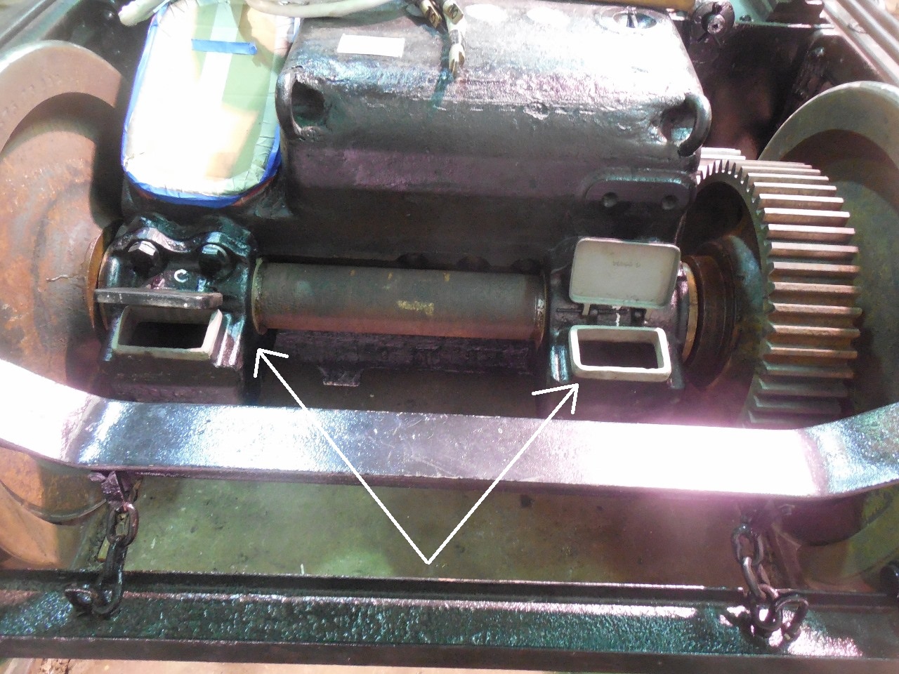
The lids are open on the axle cap, so waste can be inserted.  The waste rubs oil onto the axle's bearing surfaces.


This particular truck has outside-hung brake shoes.  Most later designs have inside-hung brake shoes; outside-hung brakes take up more room, I suppose, but make it much easier to check and replace worn brake shoes.


And this big square chunk of steel and copper, weighing about 2 1/2 tons, is the motor.  The cardboard cover on the left is a temporary replacement for the actual motor cover over the commutator.  We've seen pictures of commutators several times before.  The armature shaft runs through the center of the motor, parallel to the axis of the wheelset.


And on the gear side, the pinion is attached to the armature shaft.  The pinion permanently meshes with the gear on the axle.  Mechanically, this system is very simple, with no type of clutch, meshing, variable ratios, or other adjustments.  I didn't try to count teeth, but this motor has a very low-speed, high torque gearing, designed for use in pulling trailers; the gear ratio is about 1:4.  By contrast, the CA&E wood cars have a gear ratio of 5:8 (either 20:32 or 25:40, depending on wheel size) for high speed.  That's a big difference.

Of course, in service these gears will be covered with the gear pan, which holds the grease needed for lubrication.  It's much easier to see what's going on without it, though.

The arrow points to the door over the armature bearings, which you can open to check lubrication and add oil.  This is the same design as on the GE-66, which I hate.  When the motors are under the car, it's very difficult to open the door, which is cleverly sprung to try and cut off your fingers, and see where anything is.  Later designs are much more user-friendly.


And we finally get around to the third point of suspension: the nose, which is just a projection of the cast iron motor frame.  It's sitting on a bracket attached to the frame of the truck.  One drawback of the original Sprague design is that half of the weight of the motor is carried directly on the axle, and is therefore unsprung.  Later truck designs, such as for PCC cars or the Electroliner, modified this so that nearly the entire weight of the motor is carried on the truck.


Along the side of the truck, we see the leaf springs (green arrow) which support the truck bolsters above the lower transom and absorb much of the shocks of travel.   (These particular leaf springs don't appear to be located quite properly, but that can easily be adjusted.)  And since this is a rapid-transit car, we also have the lead to the third-rail shoe (red arrow) and the brackets for holding the third rail beam (black arrows), designed to be easily adjustable.  As the wheels wear down, the height of the third rail beam may need to be changed.  On second thought, we probably won't bother.

You will also observe that this truck has no equalizers.  Each journal box supports the truck frame directly via two coil springs.  At higher speeds some form of equalization is generally considered a necessity, so this is sort of an obsolete design.  (Well, sure, everything we work with is obsolete, but some more than others.)


The brake rigging must be designed so that the truck can swivel quite a bit on sharp curves.  This is provided by the circular bracket on the inside end of the truck.


The top rod for this truck is just lying on the frame for the time being.  It has a wheel at the end so that the truck can swivel while the brakes are applied without trouble.  The other end of the top rod, which attaches to levers on the car, is visible in the picture above.


By the way, the nose also needs to be held so that the motor cannot raise itself up out of the truck, which depends on which way we're going.  The bracket for doing this is sitting on top of the motor, but will be bolted on.  You can also see the four electrical leads for the motor.  To me, they look much longer than necessary, but there must be some way to keep them out of trouble.


Finally, the arrow points to one of the swing links.  These support the entire weight of the carbody.   It would be a challenging exercise to try to explain in words exactly how the weight of the car is transferred from one part to another to another to the wheels, but not today.

I hope this was helpful for those of you who haven't had the marvelous opportunity to work on these things in real life.  Remember, the door is always open.