Richard Schauer took the time and effort to give us a virtual tour of the AEM-7, as a contrast to the much older GG1.
All images are copyright by the photographer and may not be reproduced without permission.
(Just to remind you what it looks like from the outside, here's one of my photos:)
01. We start in the Rear cab. Wide shot of the engineer's position.
02. Engineer's position, tighter shot.
03. Engineer's position straight ahead, showing console.
04. Fireman's position.
05. Console right side. Brake handles are red for automatic brake, black for independent.
06. Console left side. Controller at bottom.
08. Fault display is backlit with each message in a little light-blocking box. Very hard to illuminate more than a few for photo, but you get the idea. Note misspelled "auxilery" in a few places, those Swedes!
09. Cab signal aspect display unit.
10. Traction motor ammeters and catenary voltmeter.
11. Engineer's back corner.
12. Controller at position 0. This controller only has a detent at 0, the coasting position. The quadrants are stepless in both power and brake.
13. Controller at full power, position +10.
14. Controller at full brake, position -6.
15. What passes for a builder's plate.
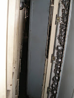
16. Entering the machinery room. Left side, facing front end. Width clearance through the doorway is 19 inches.
17. Just past door. Air compressor on right, S7 cubicle with breakers and cutouts ahead. This and all following photos except 22 in the machine room are taken from my chest height.
18. S7 cubicle detail.
These are mostly breakers for auxiliary functions.
19. Turning around and facing down. Air compressor behind commode. Still a full roll of paper on the holder!
20. Air compressor, although most of what you see is just the receiver tank. #2 traction motor blower partially in view at left.
21. View from commode.
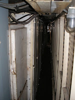
22. View of corridor from about 6-foot level. There is no place within the machinery room corridors where I can stand without stooping. General clearance is about 6 feet, with shorter sections here and there.
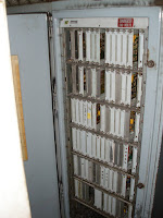
23. Motor cutouts and battery charging controls. Standing directly in front of this panel with your back against the wall (stooping), you have about 10 inches clearance to the panel. Far-sighted people need not apply.
25. Label for the Y1.1 propulsion converter. The traction motors are 900-volt machines and have separately excited fields at much lower current than the armatures; maximum armature current is 2250 amps. This locomotive is rated for 7000 continuous horsepower.
26. Looking back toward rear cab.
27. #1 traction motor blower, but the little piece of East Coast life someone left us is more interesting.
28. Front cab, engineer's position.
29. Fireman's position. The seat is out of position at the moment from cleaning up the cab after its en-route vandalism.
30. Back of cab. The
front cab has this large box containing the ACSES cab signal controls rack.
31. Entering right side corridor, looking toward rear end. HEP plant is at right.
32. Controls for HEP plant. Rated 500 kW, it was a bit weak for longer trains. Although propulsion power could be MU'd, HEP could not and was only supplied by the lead locomotive. AEM-7's that were gutted and converted to AC propulsion got 1000 kW HEP plants.
33. What's behind those doors, typical shot. This is inside the HEP converter. Lots of capacitors in front.
34. The actual thyristors and diodes are packed behind stuff and hard to see; this diode is probably the easiest. It's the gray ridged hockey-puck in the middle of the frame. All of the power semiconductors in this locomotive are oil-cooled.
36. Another photo of the guts. Note short white tubes with nuts at the ends on left side, running between round objects. The tubes are oil lines, and there are thyristors packed in behind the clamps. Large white cubes top and bottom are fast-acting fuses.
37. (omitted)
38. Hand brake in front of transformer tank.
39. Diagnostic panel. The meter can read various voltages and currents in the propulsion system.
43. Air compressor. Rotary screw compressors are very small for their air output, and most of what you see is the auxiliary stuff supporting it.
44. Air brake equipment rack.


1 comment:
Having worked with a variety of non-rail electrical equipment, this is an insanely interesting series of photographs...thanks for posting. I have a dream of someday pulling the guts from a unit like this or an ALP44 and bringing a GG1 back to life, similar to UP's GP38-inspired E9s. Imagine a fan trip in North Jersey behind an operating GG1...
T. Rich
Post a Comment