Since the motor truck for car 24 is sitting in the shop, waiting for a few final parts and adjustments, it provides an excellent opportunity to look at how a truck is put together, when everything is nice and clean and not covered with a hundred years' worth of grease and dirt. This particular truck is a relatively early design, so it has some aspects that differ from the more familiar types used on the North Shore or CA&E cars, or the CRT 4000's. We'll see what those are as we go along.
The most fundamental part of the design is the mounting of the motors. When Frank Sprague developed the nose mounting back in 1888, the electric car became reliable and practical. The motor is suspended at three points: two axle bearings and one nose bracket on the truck frame.
Looking at the axle, we see the two bearings, as well as the gear. The axle bearings are held in castings called axle caps that bolt onto the motor frame, and thus keep the position of the axle fixed relative to the motor. As the wheelset moves up and down in the truck, the motor moves with it.

The lids are open on the axle cap, so waste can be inserted. The waste rubs oil onto the axle's bearing surfaces.

This particular truck has outside-hung brake shoes. Most later designs have inside-hung brake shoes; outside-hung brakes take up more room, I suppose, but make it much easier to check and replace worn brake shoes.

And this big square chunk of steel and copper, weighing about 2 1/2 tons, is the motor. The cardboard cover on the left is a temporary replacement for the actual motor cover over the commutator. We've seen pictures of commutators several times before. The armature shaft runs through the center of the motor, parallel to the axis of the wheelset.

And on the gear side, the pinion is attached to the armature shaft. The pinion permanently meshes with the gear on the axle. Mechanically, this system is very simple, with no type of clutch, meshing, variable ratios, or other adjustments. I didn't try to count teeth, but this motor has a very low-speed, high torque gearing, designed for use in pulling trailers; the gear ratio is about 1:4. By contrast, the CA&E wood cars have a gear ratio of 5:8 (either 20:32 or 25:40, depending on wheel size) for high speed. That's a big difference.
Of course, in service these gears will be covered with the gear pan, which holds the grease needed for lubrication. It's much easier to see what's going on without it, though.
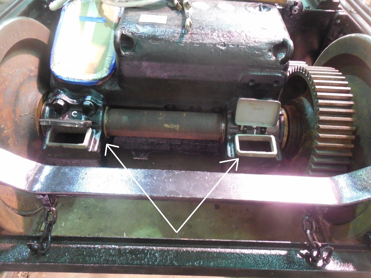
The arrow points to the door over the armature bearings, which you can open to check lubrication and add oil. This is the same design as on the GE-66, which I hate. When the motors are under the car, it's very difficult to open the door, which is cleverly sprung to try and cut off your fingers, and see where anything is. Later designs are much more user-friendly.

And we finally get around to the third point of suspension: the nose, which is just a projection of the cast iron motor frame. It's sitting on a bracket attached to the frame of the truck. One drawback of the original Sprague design is that half of the weight of the motor is carried directly on the axle, and is therefore unsprung. Later truck designs, such as for PCC cars or the Electroliner, modified this so that nearly the entire weight of the motor is carried on the truck.

Along the side of the truck, we see the leaf springs (green arrow) which support the truck bolsters above the lower transom and absorb much of the shocks of travel. (These particular leaf springs don't appear to be located quite properly, but that can easily be adjusted.) And since this is a rapid-transit car, we also have the lead to the third-rail shoe (red arrow) and the brackets for holding the third rail beam (black arrows), designed to be easily adjustable. As the wheels wear down, the height of the third rail beam may need to be changed. On second thought, we probably won't bother.
You will also observe that this truck has no equalizers. Each journal box supports the truck frame directly via two coil springs. At higher speeds some form of equalization is generally considered a necessity, so this is sort of an obsolete design. (Well, sure, everything we work with is obsolete, but some more than others.)

The brake rigging must be designed so that the truck can swivel quite a bit on sharp curves. This is provided by the circular bracket on the inside end of the truck.

The top rod for this truck is just lying on the frame for the time being. It has a wheel at the end so that the truck can swivel while the brakes are applied without trouble. The other end of the top rod, which attaches to levers on the car, is visible in the picture above.

By the way, the nose also needs to be held so that the motor cannot raise itself up out of the truck, which depends on which way we're going. The bracket for doing this is sitting on top of the motor, but will be bolted on. You can also see the four electrical leads for the motor. To me, they look much longer than necessary, but there must be some way to keep them out of trouble.

Finally, the arrow points to one of the swing links. These support the entire weight of the carbody. It would be a challenging exercise to try to explain in words exactly how the weight of the car is transferred from one part to another to another to the wheels, but not today.
I hope this was helpful for those of you who haven't had the marvelous opportunity to work on these things in real life. Remember, the door is always open.


2 comments:
Northwestern Elevated Railroad 24 had a Gear Ratio of 52:21 as built. It was a locomotive car designed to pull trailers. After conversion to Multiple Unit Control, where trailers were still used in conjunction with additional motor cars, the ratio was changed to 56:17.
Bill Wulfert
According to "From Horsecars to Streamliners - An Illustrated History of the St. Louis Car Company" by Alan R. Lind the motor truck is:
Truck No. 32.
"Hedley Patent" Motor Truck
Solid steel side frames, connected at ends with tee cross bars and corner plates; machine fitted. Channel iron box bolster, connected by top and bottom plates. Two double elliptic and eight coil springs at each side. Outside hung brakes with slack adjusters. Pull is from live to dead lever. Draft rod is arranged with coil release springs and adjustment. Arranged for two motors. Adapted particularly for elevated and high speed interurban service. Wheel base, 6 ft. Weight, 10,000 pounds.
Bill Wulfert
Post a Comment